ReactorForge
-
Posts
47 -
Joined
-
Last visited


-

Home build induction heater
ReactorForge replied to Daniel.85's topic in Induction Heating, Oil forges, etc
I hear you guys! I'm glad to be able to put time into this again as well. Happy New Year! -
Home build induction heater
ReactorForge replied to Daniel.85's topic in Induction Heating, Oil forges, etc
Another video, this one goes over the basic functionality of the machine. Not how to use it but more how it works on a high-level. I'll be making videos of each component/system and how they specifically work individually, this is more a walkthrough of how they all work together. (And don't worry, I'll get a microphone before making those videos.) Have a great weekend everyone! -
Home build induction heater
ReactorForge replied to Daniel.85's topic in Induction Heating, Oil forges, etc
Video Update for 12-29-2017 (You can also view on YouTube for the full post.) -
Home build induction heater
ReactorForge replied to Daniel.85's topic in Induction Heating, Oil forges, etc
Work takes fuel! -
Home build induction heater
ReactorForge replied to Daniel.85's topic in Induction Heating, Oil forges, etc
I've really missed working on this project and I hope that soon others will be able to make use of it! I just wanted to post a couple updates here. ] I've got it hooked up to a decent chiller now. No more pond pump and the 5-gallon bucket with a small computer fan radiator. Although that worked quite well. I also set the whole thing up on a rolling metal cart from Sam's Club. This was perfect, lots of room on the bottom for the chiller, a small area for spare coils and a shallow top for the induction heater to sit. I'm now working on the firmware. "To Infinity and Beyond!" - Buzz Lightyear -
James, You were interested in using ferrite material to focus the induction heaters flux. This site shows the application of EMS for SolidWorks to model the magnetic flux density in the radial ferrite cores under an inductive cooking coil. There are other programs you can use to model various magnetic characteristics such as MATLAB https://www.emworks.com/blog/induction-heating/induction-heating-engineers-empower-chefs#comment-9491 Two amusing things about this site's post though, for one they plagiarized a screenshot from one of my youtube videos (the very first photo in the post), and two they called the ferrite cores iron cores. This note was requested by ReactorForge: I see now that rather than saying "Two amusing things about this site's post though" I should have worded it like, "There are two amusing things about the post from the site linked above." If they were made of iron, they would burn the coils up as iron would succumb to i2r heating from the induced eddy currents. Here is another company that specializes in controlling magnetic flux distribution in induction heater work coils. https://fluxtrol.com/magnetic-flux-control-in-induction-heating
-
You are very welcome my friend. Those videos were interesting. Here at 5:58 you can see the animation of how the ferrite material carries the lines of flux. That second video cool as well. It's intriguing how the ferrite material was incorporated into a sort of clay or foam that you can mold onto the coil, allowing you focus the flux on one side. It looked like it started to get hot and smoke in the end though, or maybe that was just smoke rising from the metal. Whether it's a permanent magnet or an induction heater coil. Any time you introduce a ferromagnetic metal (iron, nickel, or cobalt) to its lines of magnetic flux (called a vector field), those field lines want to flow through the material with a higher relative permeability. Since those ferromagnetic metals have a much higher permeability than the surrounding air, they choose this as the "easiest" path to traverse. Similar to the way electrons prefer to flow through the path of least resistance. CORRECTION: In a previous post I mentioned that a variac provides isolation from mains. I want to point out that only an isolation type autotransformer or a separate isolation transformer in front of the variac will provide this isolation and most variacs are only autotransformers. You can ask the google machine for more info if you want it.
-
ReactorForge changed their profile photo
-
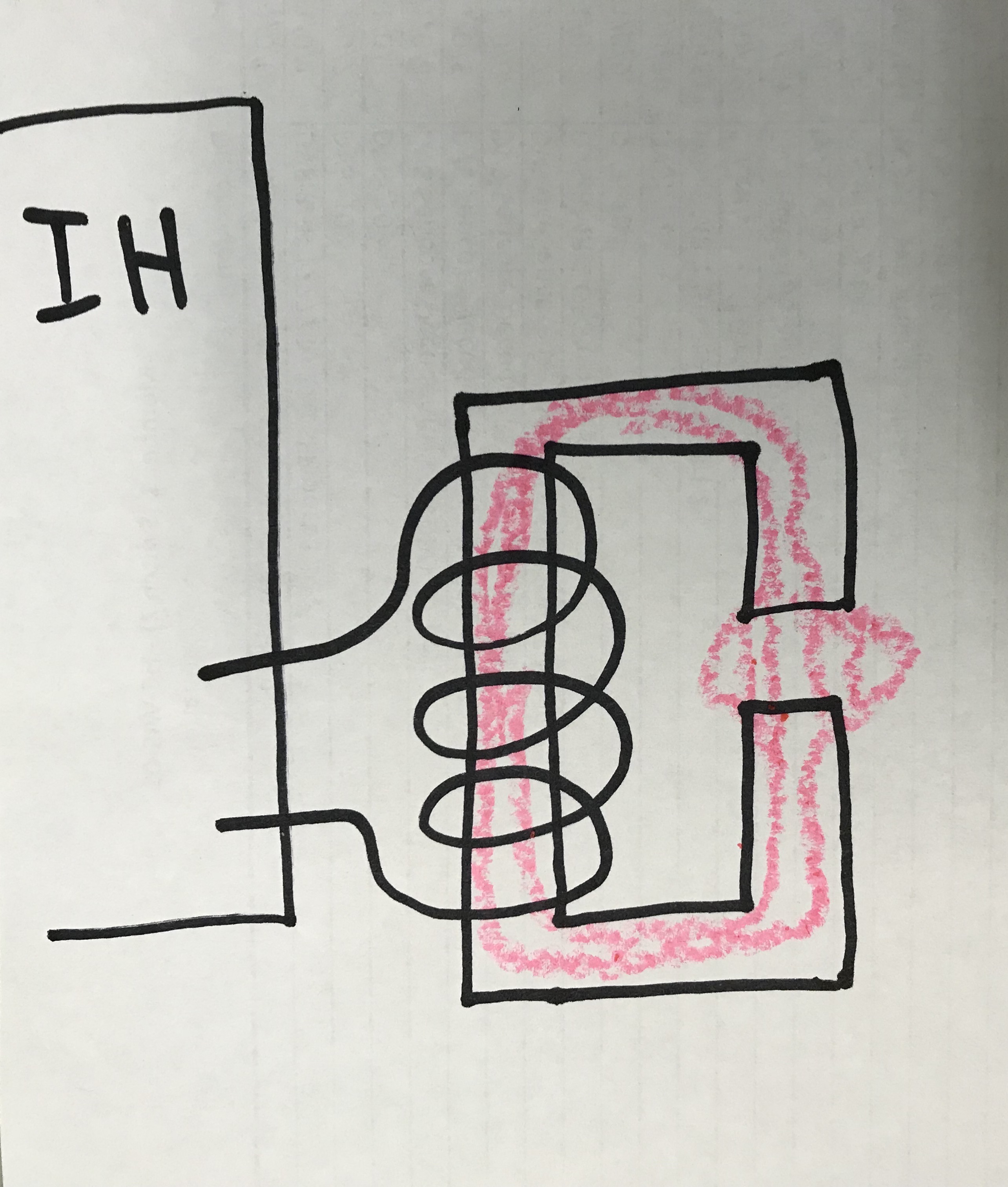
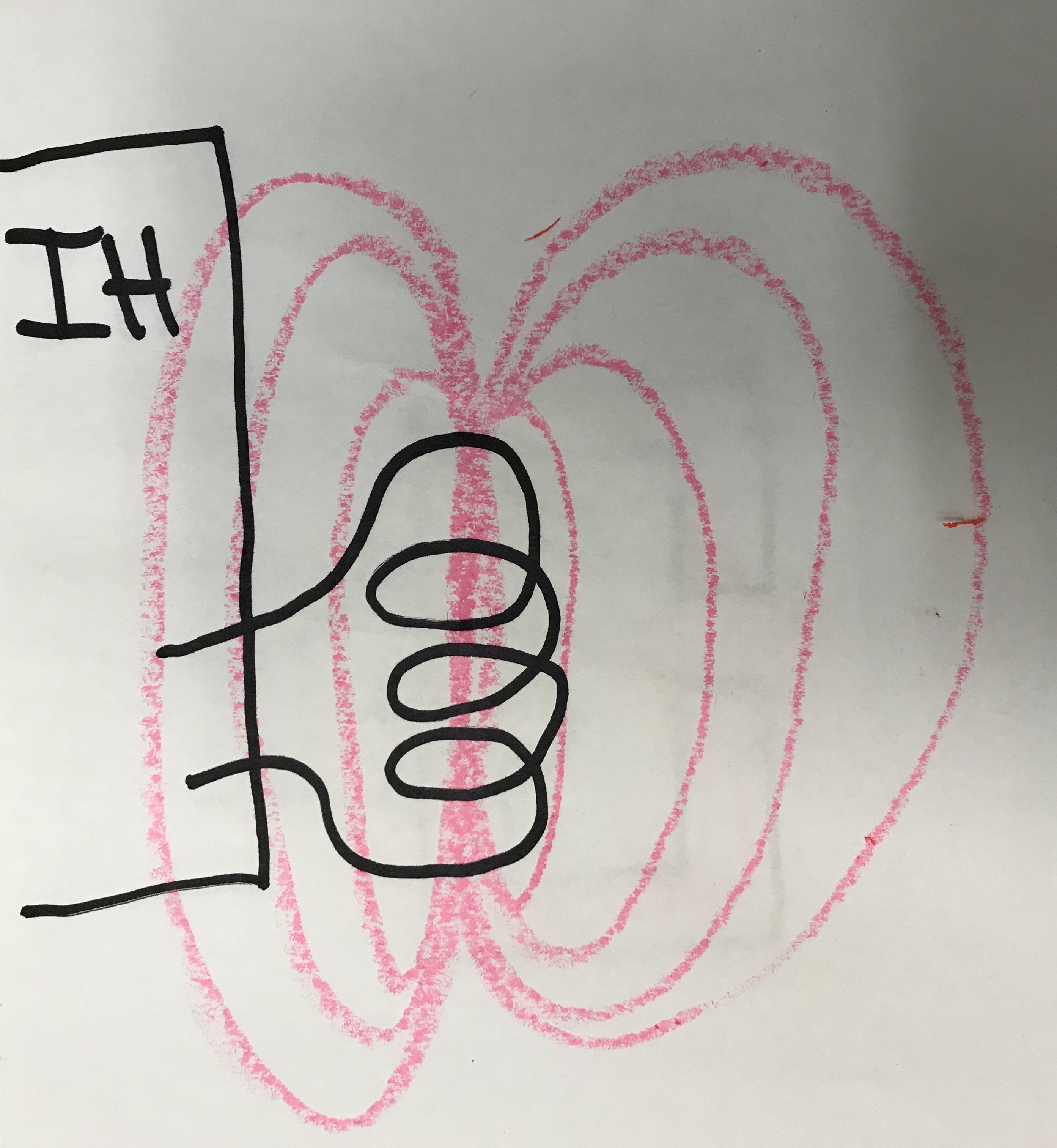
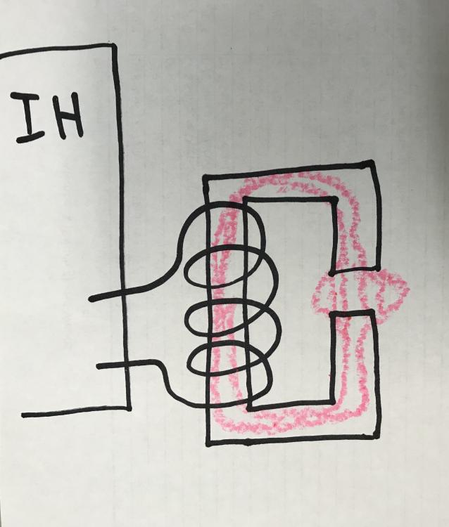
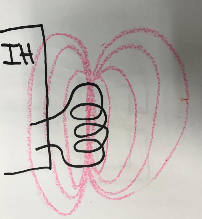
Don't underestimate yourself. Some of times greatest minds were self-educated! You're doing a great job, just be safe, keep failing, and keep learning! You won't run into too many people on the streets who specifically "know about" induction heaters but that doesn't mean you can't confer with other like-minded people about electronics in general. The induction heater circuit overall is a very fundamental and beautiful thing really. It's like nature wanted it to exist! My email is on my Github page. Shoot me a message, I have a book I want to send you that will help. Yes, there is a material you can use to concentrate the magnetic lines of flux called ferrite. It's the same or similar material used in your matching transformer. It doesn't heat up as nearly much as say a ferrous piece of metal would because it's ferrous particles are isolated from each other with a ceramic thus preventing eddy currents and I^2R heating. John DeArmond with fluxeon.com (NeonJohn) uses this in one of his models calling it a flux concentrator. It works basically like this; the crude drawings show the magnetic lines of flux in an induction heater coil with an open coil and one with a "flux concentrator". If you use this method you must take into account the fact that the ferrite "loads" the work coil much more than any workpiece. You must account for this by changing the impedance of your matching transformer (fewer turns on the secondary, more on the primary, etc etc). It also lowers the resonant frequency of the tank so you might even need a lower value capacitor to raise it back up, unless you want it lower... It's an interesting thing to experiment with, I recommend it. I don't really recommend it's use in a metalsmithing role but it does have its advantage. For example, it's amazing for brazing small parts, like copper tubes to make other induction heater coils. Yes, current sensing to determine the power consumption of the induction heater overall should be done on the mains side, the input line. Current sensing on the inverter side would give you the oscillating current of the tank. That's the big number you see on the front of most induction heaters that usually ranges from 200-800 called the "working current". A current transformer on the inverter side also gives you the ability to do current zero-cross detection of the tank. Compare this to the voltage zero-cross (your inverter switching time) and with some clever use of timers you can deduce the resonant point without a PLL!
-
Home build induction heater
ReactorForge replied to Daniel.85's topic in Induction Heating, Oil forges, etc
I was never that, but a little insanity is great for the creative soul. Or vice versa... -
Bandwidth - I never really thought of it as a waste of bandwidth, I did leave out the photo. Even though the quoted text was directly before my post, I like to make sure the context of my writing is known. But I won't do that on your topic anymore. Also, the window has closed for me to edit it so only a mod can remove it now. I don't want to delete the post and resubmit it because then things would just be out of order. Maybe we take bandwidth for granted in this country sometimes! Mod addition: Since you are not aware, let me inform you that many of the over 150 countries we service are places that still have dial up, and pay by bandwidth used. In the USA many take it for granted having high speed and unlimited bandwidth, Others do not have this luxury, try to be considerate of others, --- Point 1: Yes a variac! Very helpful in testing WHEN things go wrong. Your parts are less explodey if the variac is turned down lol. (I only asked because of the alligator clips on the rectifier, the only time I see that on mine is when the variac is hooked up.) Point 3: You're good. The small snubber capacitors on the IGBT's are necessary to suppress high transient voltage spikes on the bus during switching. They are too small to have any noticeable influence on power factor. Note: You probably already know this, but you can use an oscilloscope to view the power factor since it is just the true power over apparent power or the cosine of the phase angle delta between voltage and current waveforms (see photo). You just need a current transformer on the mains with a burden resistor and two scope probes, one on voltage and one on the CT. Point 4: Yes these are very expensive to buy completed, but it looks like you have the means make PCBs. I included the board files, BOM and description in the wiki for the open source hybrid driver I'm using here: https://github.com/ThingEngineer/ReactorForge/tree/master/hardware/Hybrid Driver You can buy the ISOLATED_DC_DC_CONVERTER and HYBRID-IC-IBGT-GATE-DRIVER at a decent price from China (https://www.alibaba.com) for example and the passives from where ever. If you want to go to higher power levels, you don't have a choice. The TON and TOFF time delay with a GTD will not work under extreme load. Your IGBTs will likely shoot through and explode. I'm not saying it's impossible with GDTs, but it's much easier, cleaner, and safer with hybrid drivers. Point 5: I'm working on a neatly documented write up (Instructables style) on precisely this to post on the ReactorForge website. It's the key to being able to make an IH that will be useful in a real shop no just on the bench for hot metal porn. The PLL is too restrictive, one could say that implementing digitally controlled passives could expand the PLLs dynamic range but that is just complicating an already complicate and sensitive circuit in my opinion. PIC makes excellent chips too, but they don't yet have a comparable power stage controller unless you count the fact that Microchip now owns Atmel. Read more about them here: AT90PWM216-316_Datasheet ATMEL PSC Cookbook Application Note Point 6: Similar to the gate driver issue, this is needed even more so at higher power levels. You're very welcome and keep up the good work.
-
Great job James! It looks like you have tackled most of the challenges you faced in the beginning, a significant step indeed! I see a few things I want to point out that helped me and hopefully, they will help you too. I am close to publishing all the info about the ReactorForge on GitHub and the website. But you have come a long way, and yours is the closest I've seen to what I built, so I wanted to share this much at least. I'll start with the mains input and work my way to the work coil. I'm sure it's just a test setup, maybe you had a variac hooked up in this photo, but definitely up your wire gauge into the rectifier. Pulling 25 amps at 240 volts is more than enough power to heat up wire that size and melt the solder joints on those alligator clips. Again I'm sure you knew this already. Join the rectifier to the IGBT bus using the same copper strips you used to join the two IGBT's together to lower inductance even further on your DC bus. Speaking of DC, kudos on not using a filter cap on the DC busbar. The IGBT's and tank don't mind that 120Hz pulsing DC, and it helps maintain a power factor closer to unity! It looks like your still driving your IGBT's with gate transformers. They are great for a lot of things and easy to work with, but I highly recommend switching to a hybrid driver. They are much safer and will extend the life of your IGBT's. Preventing a crowbar, "shoot through" situation among other features is critical when you are pushing the limits of power in a noisy environment. If you are still using a PLL to lock onto your resonant frequency, you are limiting your dynamic range of the coil size, workpiece load, etc. In short, the inductance of the work coil is restricted since your passive components lock you into a tuneable range like in imsmooth's circuit here http://inductionheatertutorial.com. It is also affected by extreme swings in ambient temperature depending on your passive elements and layout. I've got an excellent method using an Atmel power stage controller as a pseudo software PLL. It has the added benefit of allowing you to monitor for many other types of situations in software as well. I'll be sharing all my code for that on GitHub soon too! (I will likely make individual repositories for the new cleaned up versions.) You are using the tank capacitor voltage for your resonant control logic. While there is nothing explicitly wrong with this method, you would benefit by switching from monitoring tank voltage to tank current. Do this by adding a current transformer to one of the inverter legs feeding the matching transformer. As you know, the tank voltage in a series resonant setup gets VERY high! From a signal conditioning perspective, this is an irritating and inefficient problem. Using this method you also get the added benefit of being able to monitor inverter current if you split and condition your signal correctly. Check out the schematic of the ReactorForge CriticalMass for an example of one way to accomplish this. Your matching transformer appears to be a bit small and is probably saturating at high power levels (or likely will if you try to go beyond 6KVA). (Usually indicated by distorted secondary output.) You can stack multiple E cores to increase flux density and make sure to use a ferrite material rated for high frequency (at least 100Khz) such as 3C85, 90, etc. and have a high AL value. Operating in a constant or occasional saturated state isn't necessarily a deal killer as many Chinese units tend to run like this. This use of this method is one reason why they have copper plates and cooling lines on the transformers. I think this is a cheap cop-out way of driving the tank though. The tank bus lines need to be closer together. You are introducing a lot of inductance and wasting power as well as heating up any surrounding metals including the lines themselves, transformer, capacitor, etc. The series topology can be a difficult one to get the lines close, but it's doable. Something like this is what I used: https://imgur.com/a/oWSK6 I also noticed your LCD display says "POWER 0%". I know you aren't monitoring the mains or inverter current (at least not in this photo) but are you control the average inverter power output level? If yes what methods have you tried (PDM, Phase Shifting, Frequency Shifting, etc.)? The issue of power control get's interesting at very high power levels, generally above 8-10KW or so. Keep up the great work James! I can't wait to see how far you take this next year. - Joshua Campbell
-
Home build induction heater
ReactorForge replied to Daniel.85's topic in Induction Heating, Oil forges, etc
Hey all, I just wanted to get on and personally thank everyone on I Forge Iron for their patience, even if you had none which is totally ok! I have had a lot of changes personally some really good and some difficult. For the last 4 years, I've run my own business, raised teenagers, and have done way more traveling than I care to do. I never gave up on the open source high power induction heater, ReactorForge, but it had to be put to the side for a while. I'm still extremely busy but I am finding ways to manage my time that will allow me to be with my family more and work on this awesome project! I'm not asking for financial support, this project is moving forward with or without it, if you choose to be a patron I thank you. However, your feedback and suggestions will be invaluable. I'm not a metalsmith and I don't want to just guess at what is best for all of you, right down to the size and placement of the last button and screw. I encourage everyone interested to +FOLLOW me on Patreon for regular updates, there is quite a bit of information on there already if you haven't checked it out yet! I might also make a new thread on here if that is ok. Forge Ahead!!! -Joshua Campbell
-
Home build induction heater
ReactorForge replied to Daniel.85's topic in Induction Heating, Oil forges, etc
There are many differences that it makes, you have to weight a handful of variables to determine what is right for your application. There is a massive amount of current flowing in that coil therefor any resistance of the coil generates heat. Smaller size = greater resistance = more heat. With the smaller size comes a reduced coolant flow which also adds to the heat build up issue. Put simply you can go smaller if you can keep it cool. The smaller diameter allows for tighter/closer turns which can contribute to a more uniform heating of the work piece. The smaller diameter tube is easier to bend without damaging it and can be bent into smaller and more detailed forms. -
Home build induction heater
ReactorForge replied to Daniel.85's topic in Induction Heating, Oil forges, etc
I'm trying respect the rules here and not to cross the line of promoting a product so there is a lot I'm not going into here, just answering questions. But yes we are shooting for well under $2K for a raw kit and a bit more for an ARU kit (almost ready to use). Basically an hour of your time, and a screw driver or allen wrench then your ready to go, no soldering or any complex assembly. All individual components and modules for the ARU kit are being QA certified in a working test bed. We are also exploring a kit assembly option and will be offering multiple warrantee levels. This machine is over build, where as most overseas 15-25KW units are built with the minimum capacity parts and operate at or very near their maxim range of operation, thus the 80% duty cycle on most. That being said the Magtech's are great machines, but I very much believe I can top it in price, performance, whistles and service. :D A.) Using a coil with the fewest turns and minimum diameter will alway be the fastest way to heat. Of course that's not what I was going for in that video. Eventually I'm looking at doing an application request video each week for an induction heating application with the highest votes. 1.) Looking at heavy duty die cast aluminum most likely. And possibly a couple options as not everyone will need an industrial strength version. 2.) Yes, I'm using one massive 2 pole 240v contactor to interrupt mains voltage to the high power section when it's not in use. It's in an easy to replace area and can be done with just a screw driver. Replacements for that contactor should be in the $10-20 range. On a similar note since it seams like you have experience with this, the contactor is never switched under load, so unless the coil fails it should never need replacing. 3.) The case design we are implementing does provide easy access to all sides, however, the unit is 100% sealed now. Internal ambient temperature stays within a degree or two of the cooling water temperature (even in a 90% shop running at full capacity). I couldn't not do this after seeing the results of shop use on one of the prototypes Daniel was using. 4.) I'm making progress on the optical pyrometer theory and model and will be working on a prototype soon (the forge needs to come first obviously). There are some very low cost sensors that I believe will make this project doable. I would love to be able to offer a decently accurate pyrometer for around $50-100, and as it stands that is plausible. -
Home build induction heater
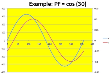
ReactorForge replied to Daniel.85's topic in Induction Heating, Oil forges, etc
How many KW will these unit's be? - They will be marketed as a 15KW machine. That is in reference to the oscillating power in the tank circuit. It not a good rating system in my opinion but it's the one adopted by the industry (and many others). The actual input power in volt amps is about 7-8KW that's 208-240 volts @ 32-34 amps. See the two units below for reference, it doesn't mater if they are Chinese, Russian, or America, most all of them rate their machines like this. http://www.magtechina.com/products/234.htm http://www.acrossinternational.com/15KW-Mid-Frequency-Split-Induction-Heater-w-Timers-30-80KHz-IH15AB.htm (Notice the duty cycle as well on these, 80%.) I prefer rating by application like Grant did with his machines, calling them 1.5" machine, 3" etc. I've seen 15KW Chinese units that could not heat a 1" bar to much past a bright red (1600-1700℉). Showing what the machine is capable of in real world applications is the only way to really know what your are getting with these things. That being said, since this machine is overbuild to ensure long life and reliable performance in the face of constant use, it can be safely "over driven" to about 75 amps. Also most units have a power factor of 0.6 to 0.75, this forge however runs at a near unity power factor of 0.99. See here for a description of power factor and what it means for efficiency. The forge operates best in the mid-frequency, industry term for 30-80KHz. However it's full operation range can span from audible frequencies to about 120KHz max. In the video below it is running at 50KHz. At that frequency the penetration depth of iron is about 0.009 mm or 0.000362 inches. That is amount of material on the surface of the work piece that is receiving the bulk of the energy from the magnetic field. Keep in mind that as frequency varies from 20 to 100KHz, for example, the penetration depth only fluctuates by 0.008 mm or .000316 inches. Power control can be just as important, to much power even at low frequencies can still damage the surface of the work piece. Here is an application video heating 3 inches of 1.25 inch bar stock to white hot, limiting input power to 7.6KW (about 32 amps at 240 volts). https://www.youtube.com/watch?v=4vICz4akL6k One could heat the same length of bar faster using a 2-3 turn coil then just move the bar back and forth, however I wanted to demonstrate it's capability to heat larger sections without user intervention. Handy if your working on one item and want to have the next one heating and ready to go. Plus I'm pretty sure 2 minutes is still just a little faster than a flame forge, and there are absolutely not fumes or smells (since the bar was clean). Just the smell of hot metal, which I have to admit I'm beginning to grow fond of. In reference to the previous conversation about electronics and their distance from the coil; notice how close my $250 Fluke amp meter and old iPhone are to the coil, 3 inches from the open end. And keep in mind the ends are where the magnetic lines of force extend the furthest out from the coil, just like the north and south pole of a magnet are strongest at the poles. With the coil empty (no work piece absorbing the field) the major flux lines only extend about 1.5 to 2.5 inches from the poles at full power.