

jim c
-
Posts
45 -
Joined
-
Last visited
Content Type
Profiles
Forums
Articles
Gallery
Downloads
Events
Everything posted by jim c
-
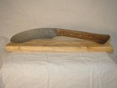 180 layers of bandsaw blade and sheet metal
 -
-
-
-
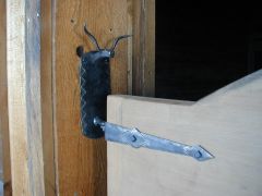
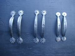 door pulls made from 1/4 x 1
 -
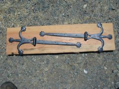 heres a set of strap hinges.. made from 1/4 x 1
 -
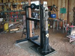 home made power hammer. made this from a toyota truck rear end. works well but just hits hard.
 -
 view of center piece
 -
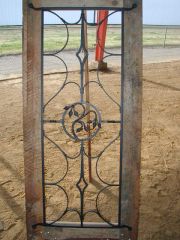 THIS DOOR GRILL WAS DONE WITH TENONS AND RIVETS AND FORGE WELDING.
 -
good morning, just signed up and trying to get a grip on useing this site. i've been smithing since 1999 and will continue for the deration. will send in some pictures as soon as i figure i out. im not good at typing!!! see ya
-
IForgeIron Blueprints Copyright 2002 - 2007 IFORGEIRON, All rights reserved. BP0229 How to Level a Drill Press to the Spindle Original Notes from Saltfork Craftsmen ABA member Adam Hall Text and Photos: Jim Carothers The problem at hand – how to accurately align the drill press table with respect to the spindle? This drill press had recently been used to angle drill some holes by loosening the bolts under the table and rotating (tilting) the table – something like tilting the blade on a table saw. It was now time to put the table back in alignment with the spindle. Since nothing in my shop is really true or exactly level, the use of a simple carpenters level would not produce an accurate alignment. Note also that the drill press table shown can only be aligned in one plane; the other plane is set by how the table and clamp were factory machined to match the drill press column. So alignment in one plane only simplifies things some. The alignment tool is made from 1/4" round bar or other very stiff wire. One end of the tool is ground to a point. Chuck on the tool and raise the drill press spindle all the way up. Make sure the spindle stays in the full up position; use the spindle travel lock if necessary. Make your best guess as to setting the table level (in align) with the spindle and lightly tighten the bolts that lock the table tilt angle. Now, crank the table slowly up the column so that the pointer on the tool is just clear of the table face – maybe 1/8” gap to start with. Turn (rotate by hand) the spindle and alignment tool 180^. Check the pointer on the other side of the table face to see if it is hitting, closer to the table, or further away from the table than your initial gap. Adjust the tilt of the table as necessary, lightly tighten the bolts again, and repeat Steps 3 & 4 until the pointer barely touches the table face at both positions. Fully tighten the table bolts. Alternately you could use a set of mechanics feeler gages or a business card as a gage to check the pointer to table gap at both sides. The use of simple gages would take care of any spring (deflection) in the pointer. If you really want to get fancy with the alignment, use a dial indicator as you would to set a milling machine head to the mill table. Adam Hall and Jim Carothers View full article
-
IForgeIron Blueprints Copyright 2002 - 2007 IFORGEIRON, All rights reserved. BP0207 Punch Holder by Jim Carothers Thanks to Saltfork Craftsmen member Bill Kendall for putting me on to the Bucket Boss Tool Roll-Up. My punches and chisels and other assorted tools have crowed a small tool box enough that I have a hard time finding a particular punch or chisel quickly. At the Saltfork meeting November 13th here in Perry, I noticed that Bill had his tools organized in a neat roll-up case. I was able to easily get all the punches, chisels, drifts, and several pair of pliers into the roll-up and still have room for more. The tool roll-up will help make things go a lot smoother at the next demo. I may even put some labels on the pouches inside the roll-up; however that might be excessive organization even for me. View full article
-
IForgeIron Blueprints Copyright 2002 - 2007 IFORGEIRON, All rights reserved. BP0206 Saw Blades By Jim Carothers I have tried a number of different reciprocal saw blades for cutting steel. Most advertise in large letters that the blade is "Metal Cutting". The fine print on the back of the package limits the use of these blades to "non-ferrous" metals -- aluminum, copper, brass, etc. -- about anything except steel. The pictured Skill reciprocal saw blade is a real Metal Cutting Blade. The "ugly" shape to the teeth helps the blade to last longer than normal blades. This is a bi-metal blade that will take a lot of flexing and not break, and it has a progressive pattern to the teeth that allow cutting of thick or thin material. View full article
