

kcrucible
-
Posts
147 -
Joined
-
Last visited
Content Type
Profiles
Forums
Articles
Gallery
Downloads
Events
Posts posted by kcrucible
-
-
Thanks for the numbers, evfreak.
-
As far as I know, it's basically just hardness... the ability of the material to keep its molecules in a given position. Thickness and/or backing helps keep the plate from simply bending, so that it's just compression of the material that matters.
You hit it. Because the metal has nowhere to go, the top molecules compress. Because of the hardness they spring back to where they were before, causing the hammer to rebound. -
Thanks Bob.
There's a few more features that aren't shown here yet (and some not yet complete.)
1) I have plugs for the forge ports if I'm just doing a crucible melt
2) I have plugs for the top exhausts if I want to do a slow annealing, etc.
3) I will be making "spacers" for the sides to lift up the top if I need a very large opening (similar in theory to opening a clamshell forge I guess)
4) A smaller burn-out chamber on top that gets fueled from the exhaust gasses to preheat my smaller molds, etc.
My blog has a lot more deliberation/thinking about the various design features, how things work, etc, than I put here.
chyan, pictures will be forthcoming! -
that's nothing new, "cut-and-shoots" have been around since guns were invented.
Hopefully it has a good safety. It'd be a shame to shoot a nice steak. -
Oh C__p Now I find a jr member(younger than me) who started 200 yrs ago.
New show... The Vampire Blacksmith. -
Nearly done now... approaching the moment of truth.
A bit more welding, stablization, and grinding to get everything to fit properly... I was less concerned about "pretty" on the welding basket than I probably should be. The extra bar for strength really helps total rigidity.
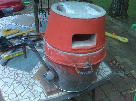
And a shot with the lid open, showing the finished insides. This hasn't been pre-baked yet so the refractory is still "green" but pretty dry.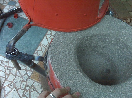
After that, time for some magic! -
Okay, cross piens are still pretty common, though usually called engineer's hammers.
Different beasts from what I can tell. An engineer's hammer is like a cross pein with two large heads and no tapered wedge.
Engineer's hammer
Blacksmith hammer
Cross Pien (same as blacksmith as far as I can tell)
Drilling Hammer (just a small engineer's hammer? looks like maybe a rectangular face also)
-
I ran across a 2.5 lb "new england style" blacksmith hammer at sears yesterday by stanley. It looks like a cross pien based on another picture I saw (not that familiar with the terminology). It had a wood handle.
More or less this one I think, but had a painted black handle.
http://www.acetoolonline.com/Stanley-Hand-Tools-56-412-2-5-lbs-Hammer-p/stt-56-412.htm
I was wrong... craftsman brand on the shelf, not stanley. Same specs though. No spiral marks on the face... the only "grain" is vertical. A bit more rounded on the face than seems a good idea if you want to do flat easily and the transition to the edges are a little abrupt. But as Bob says, modifiable. -
I ran across a 2.5 lb "new england style" blacksmith hammer at sears yesterday by stanley. It looks like a cross pien based on another picture I saw (not that familiar with the terminology). It had a wood handle.
More or less this one I think, but had a painted black handle.
http://www.acetoolonline.com/Stanley-Hand-Tools-56-412-2-5-lbs-Hammer-p/stt-56-412.htm -
Very nice. What's the inner dimensions of that forge? What's the max temp on the thermocouple? Some purchased ones I've seen seem to max out at 2400F.
Is there a reason for the REALLY LONG bar between the valve and the tip? Just erring on the side of caution for adjustability? Once you figure out the proper placement, you might consider replacing it with a shorter one so that it doesn't take up as much floor space. -
Interesting idea. Getting a big block of "Sculpy" (a plasticine) from a craft store would probably do ya. Places like A.C. Moore and Michaels will carry it. As for A.C. Moore, they regularly have 40-50% off any one item coupons in the paper, so could be pretty cheap.
-
Huh. I've never had a single problem with my bernzomatic in any orientation. Did I just get lucky with a better valve/torch assembly than typical? I'm a little surprised to hear how many people have finicky torches.
With regards to Phil Cooper's post above, I always use a flint/cap on that torch, so maybe that changes things. *shrug* -
New to the anvilling and forging biz, not new to tools.
New to welding, old hand with grinders and sanders for both metal and wood.
So, that's why I was thinking my fix would be via grinding/sanding and NOT do the welding and hardening bit, as I don't trust my skills in that area yet.
But the point that I should probably use it a bit to figure out what I want to do with it is well-taken. I may decide on different sharpnesses of corners, etc, that I may not anticipate right now. -
No doubt hands-on instruction is the best teacher. If you just want to read a bit about it, go to my site and scroll down a bit. On the left-hand side I have links to some public domain and downloadable old manuals, etc. Better than nothing! :)
-
Yeah, you definitely need more air. There's no great way to diagnose the ultimate problem without knowing more about how you made your burner and your propane supply though.
I'll start with the most obvious to me...
1) There's no forced air going on here, it's just venturi action, right? That looks closest in design to a "sidearm burner." Is this your design, or just trying to figure out how to get someone else's to work? If the latter, I think you need a hair dryer, etc, blowing into the air intake.
2) Are you using a normal BBQ Grill regulator? (small disk in between the tank and the hose) Those don't supply enough pressure to get a proper venturi effect going, where the gas pressure creates enough suction to pull more air into the tube. I used this.
3) What's the inner diameter on the gas/air feed pipe? That looks pretty big. The bigger the diameter, the slower the volume of gas, and slow propane volume = very little suction = very little air. I used 1" diamter black iron pipe. Some people use 3/4" with a smaller jet.
4) What size of jet is your propane coming out of? A welding nozzle, or a drilled hole? As in #3, a larger hole = lower pressure than a smaller hole. You can increase the pressure with the regulator to compensate and get more volume at the same pressure, but we haven't established that you have pressure.
I'd invite you to look over my burner pages. I talk a little bit about theory (as best I understand it) as well as how I made mine, mistakes, and fixes.
http://kcrucible.wordpress.com/the-kcrucible-furnace/ -
You're both probably right. For the time being I'll work with it as-is and see how much it impacts and what I want to do about it. In principle, there's not that much material to be removed to get it decent, it's just rather raggedy. For rough-forming, perfectly usable, just won't be great for finish work. There are still a couple of inches up near the horn that are still nice and, as you say, I could always deal with some haardy tools for the last mile.
-
Well, I've got the base mostly-cast as of this morning.
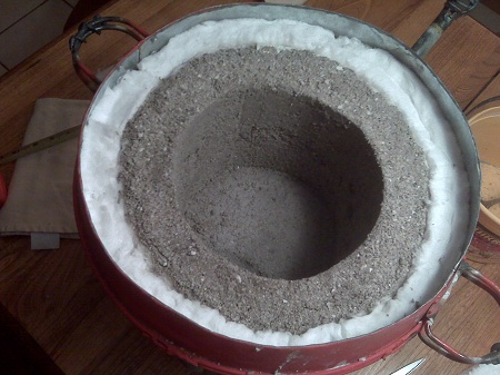
Stage 1: The bottom. 2" of inswool topped with 1" of kastolite 30. drain plug opposite the burner tube for metal spils. Foam blocks to reduce weight and amount of refractory by a small amount where it isn't really needed.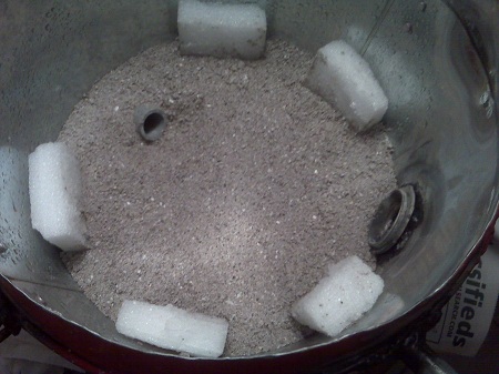
Stage 2: Build the forms using inswool and copper flashing, with foam to block off the parts where we don't want the castable to go, such as the burner inlet.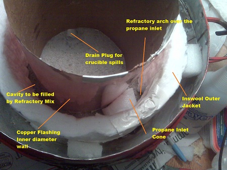
Stage 3: Filled in and curing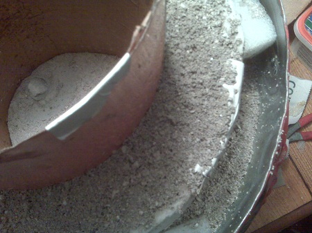
Stage 4: To be continued... filling in the gap with more inswool and then putting a refractory cap over top so that the lid can rest on it as well as seal in and protect the fibers. -
I managed to find a reasonable price on an 1881 Fisher anvil, that is generally in good shape with the exception of some pretty rough edges.
Rather than trying to build up the edges with welding, etc, I was thinking that it'd probably be effective to just use the belt sander to take off a little material from the sides to true it up. Surface area on top would decrease a little from original, but would basically be the same as current.
Opinions? -
Why ?
I guess no one gets the joke...
http://dictionary.reference.com/browse/brass
Slang brass balls "toughness, courage" (emphatically combining two metaphors for the ssme thing) attested by 1960s.
And because of the nature of the joke, someone created this:
http://www.amazon.com/Brass-Balls-Keyring-Keychain-Novelty/dp/B001PV1UK2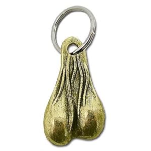
Or another alternative derivation, perhaps
http://www.phrases.org.uk/meanings/cold%20enough%20to%20freeze%20the%20balls%20off%20a%20brass%20monkey.html
There were earlier balls version - Bluestones' The Private World of Cully Powers, 1960 has: "Man, I'm so hungry I could eat the balls off a brass monkey". There's little doubt that the phrase was circulating almost the general public before WWII - some years before it appears in print.
In Arthur Mizener's biography of F. Scott Fitzgerald The Far Side of Paradise, he includes part of a letter written by Fitzgerald's wife Zelda in 1921:
"This damned place is 18 below zero and I go around thanking God that, anatomically and proverbially speaking, I am safe from the awful fate of the monkey."
Later, but still before WWII, Eric Partridge, in A Dictionary of Catchphrases, repeats this report:
Shortly before WW2, The Crazy Gang at the Palladium played a sketch wearing fur coats, hats, gloves etc. When the brass balls fell from a pawnbroker's sign, one of them exclaimed, "Blimey, I didn't know it was that cold!"
The last reference is especially pleasing to the joke since this subforum is "Cold worked metal."
And in modern usage... (skip ahead to 3:55)
http://www.colbertnation.com/the-colbert-report-videos/58887/february-09-2006/big-brass-balls-award -
Making the tooling was the work. Spinning the shells only takes a few minutes. I'm not sure where I will go with this now that I know I can make them but I'm sure I will be trying to make bigger ones....
Shouldn't those be done out of brass? -
Thanks for the feedback, Phil.
I suspect that a lot has to do with how you use your forge If you fire it up, get the job done, then turn it off there's probably not a big benefit. If you leave it running all day for multiple pieces, break for phone calls, etc, more useful. Really the idle is nothing more than just turning down the fuel input, it's basically just a convenience to keep seetings, etc.
I could see it REALLY useful as a "warming torch" for glasswork to keep the boule and partially blown piece up to temp by periodically soaking it in high temp flame. Since you wouldn't have a lot of insulation to "save" the heat, you'd want to run it as low as possible when not actually using it and since your hands are kinda full, as easy as possible to operate.
I think I'll skip the drama for now and keep plugging away on the important stuff and skip the valve entirely for now, even though it may be somewhat more convenient than the regulator. -
It's a trick for what they call an "idler circuit" for a gas forge. Basically you take your gas input and split it between two different valves. The valve on the left is a ball-valve for macro on/off, and the valve on the right is a needle valve that allows fine adjustment.
Basically you get it set up so that both are open, but the needle valve side supplies just a little bit of gas. When you take your work out of the forge you can flip off the macro valve so that only the needle valve is supplying gas, but at a very reduced rate. This keeps the forge burning without using as much propane as maintaining forge-temp propane volume. After you re-insert your work, you flip the macro valve back on to heat your piece.
It's fairly clever. I'm not sure just HOW useful it is in practice.
Here's where I first read about it.
http://ronreil.abana.org/Forge1.shtml#Close
For a far more economical forge, you should use an "idle/full" valve arrangement so that you can instantly drop your forge to a quiet idle when you are at the anvil, or tending to some other chore, such as a phone call, etc. When you return to the forge, a simple quarter turn of the lower ball valve instantly brings the forge back up to full heat. You will discover that the forge will not lose its operating temperature when in idle mode either. The idle/full schematic diagram is self explanatory, and you can easily figure out how to adjust the upper and lower gas pressures by using the needle valve and regulator for your particular needs when starting your day at the forge. Although the schematic calls for 1/8" plumbing, you may want to use 3/8" for everything except the little bypass that has the needle valve in it. If you are using more then one burner, the larger diameter plumbing will provide a better fuel flow with less pressure drop. (Thanks goes to Rex Price of Hybridburners.com for the excellent Idle/Full schematic diagram.) -
I'm sure that I'm missing something. but the last picture, what is that setup?
It's a trick for what they call an "idler circuit" for a gas forge. Basically you take your gas input and split it between two different valves. The valve on the left is a ball-valve for macro on/off, and the valve on the right is a needle valve that allows fine adjustment.
Basically you get it set up so that both are open, but the needle valve side supplies just a little bit of gas. When you take your work out of the forge you can flip off the macro valve so that only the needle valve is supplying gas, but at a very reduced rate. This keeps the forge burning without using as much propane as maintaining forge-temp propane volume. After you re-insert your work, you flip the macro valve back on to heat your piece.
It's fairly clever. I'm not sure just HOW useful it is in practice. -
Nice idea. The limiting factor will be the KW output of the burner(s). My local BBQ supplier told me that ordinary BBQ burners are rated too low to run a gas forge, but that the output from a single ring camping burner would do the trick.
It may be possible to bore out the jets in your burner if you need more output, but consult a licences gas technician so you don't make it unsafe.
Hehe. The burner is already taken care of.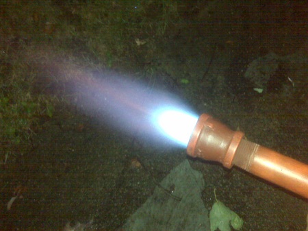
Trials and tribulations on this other thread...
But you're right, using 1 or 2 high-volume burners (like they use on turkey fryers) would probably be a decent alternative, though you'd have to figure out how to make it work on your design.
The grill didn't come with the burners anyway... probably they rusted out and rather than replace them the owners junked the grill. But the knobs seem servicable for a more convenient heat management system (1 gas input, 2 outputs.. same as the front end of a gas idler circuit... mostly.. rather than on/off on the main gas input it'd be variable, but variable in the "I can adjust it back to the same point fast" way.)
But I'm liking the grill base idea... room for the furnace + spill area/sand casting table in one package + tools on the wings. Room underneath for the propane tank and hoses are protected from spillage, etc.
Show me your anvil
in Anvils, Swage Blocks, and Mandrels
Posted
Found this one the other day, billed as between 120-140 lb Fisher for $250. I bargained him down to $200 based on the chipped edges I was planning on doctoring.


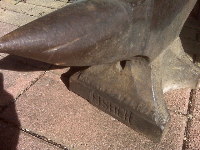
Just this morning I noticed a 161 faintly etched into the side toward the top so hauled out my scale. Indeed... it rings in at 162 on my balance scales. A little damaged, but not a bad deal I think.