

Phillip-SC
-
Posts
34 -
Joined
-
Last visited
Content Type
Profiles
Forums
Articles
Gallery
Downloads
Events
Posts posted by Phillip-SC
-
-
10 hours ago, Scott NC said:
What is your project that requires all these rings, may I ask?
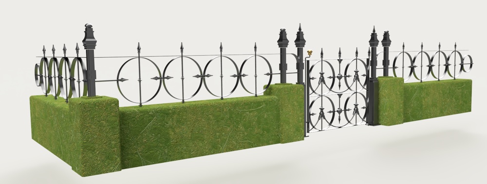
Sure, thanks for asking. It's a gate, and fence sitting on what I call a half wall. Many circles involved in about 75+ feet.
Here is preliminary sketch from a while back although it is a good deal more complex now. Actual photos pretty soon.
-
Found one simpler approach - Sometimes it IS advisable to put the CART BEFORE THE HORSE.
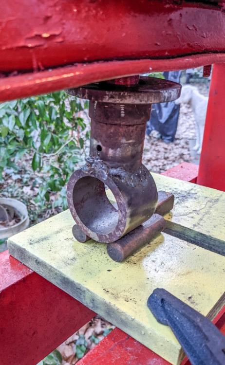
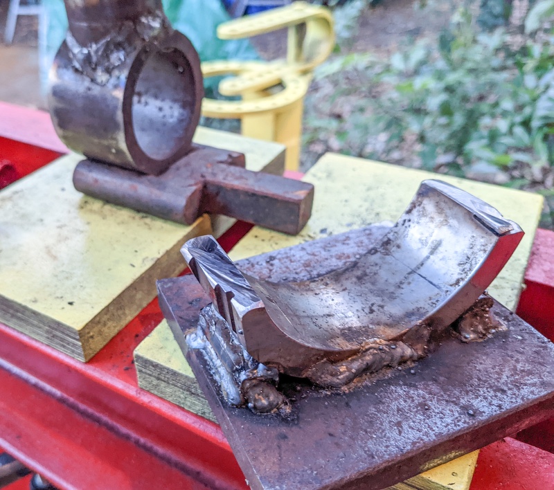
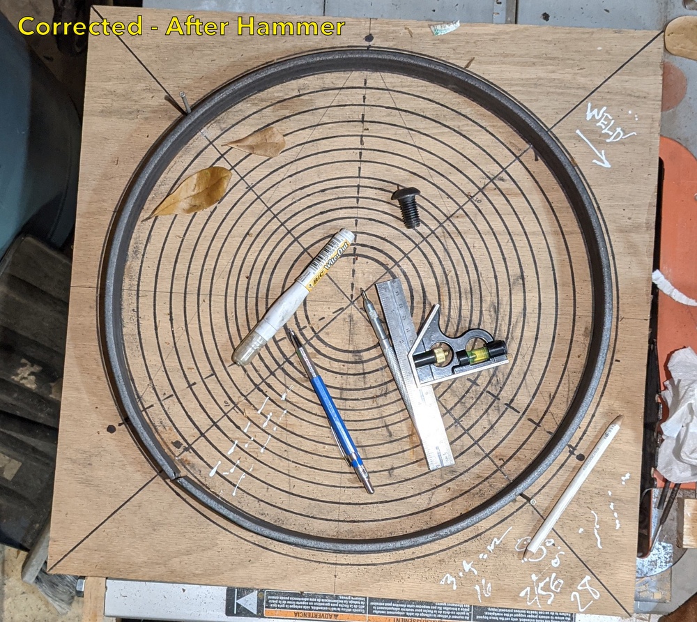
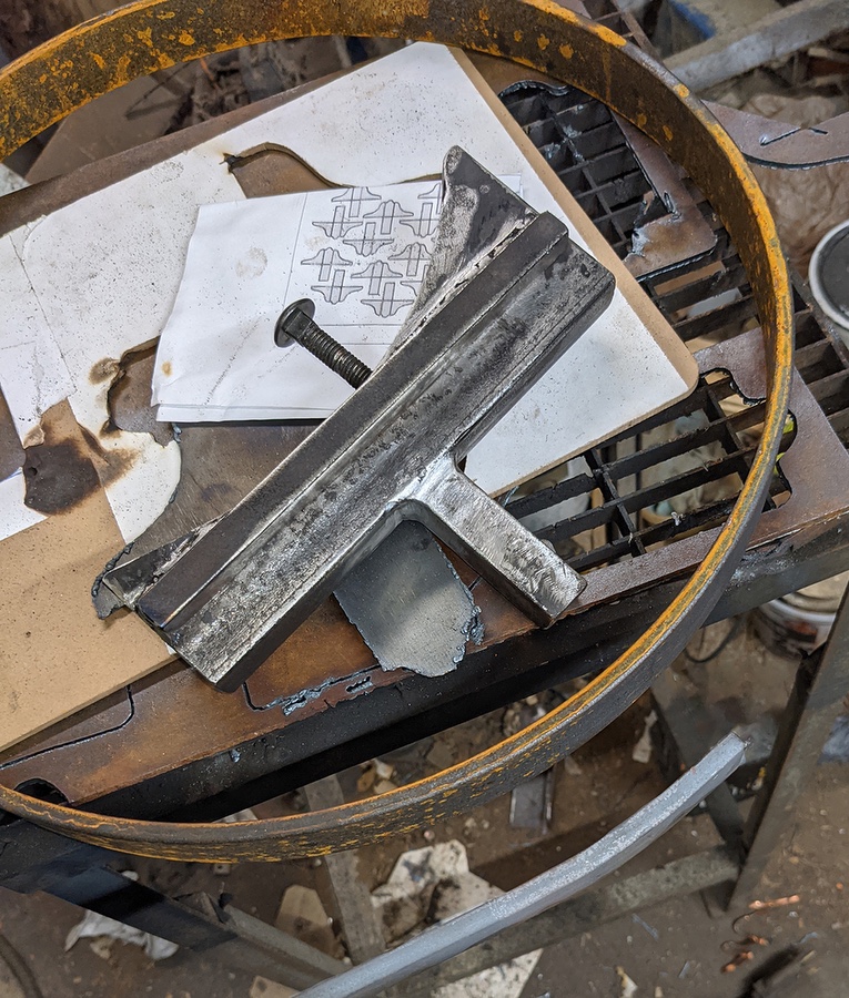
Moving along with the current project, I have found it time consuming and frustrating to PRE-bend the ends of the 47-1/2 inch flatbar/workpiece in the vise-held radius fixture.
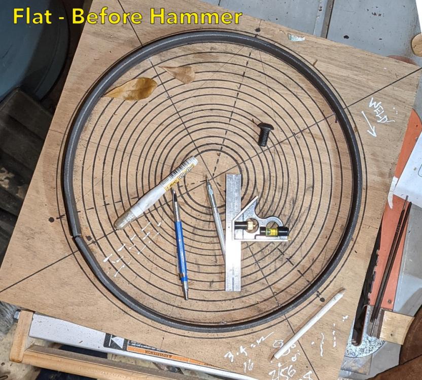
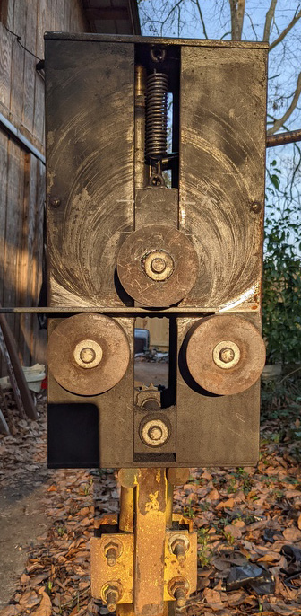
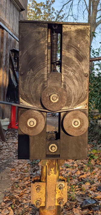
Instead, I thought about perhaps correcting the flats AFTER rolling the circle (I am certain that many of you already thought of that)... and it works really well, and fast.
These photos show the before and after of the segment in question - the whiteout pen (wonderful metal marker by the way) is kind of pointing at the area.

-
9 hours ago, Scott NC said:
I might have an even better/easier way to eliminate that flat spot on your next job with a slip in fixture for your bender, but I have to draw a sketch as I can't describe things very well, if your interested. I can pm it to you as it might be something I might make and sell myself so I can retire.....
")
Yes! Please do share that, with my THANKS! Are you thinking to simply slide in a prebent segment between rollers, then lay the ends of my workpiece over that? I think that would work -- How cool! The adjustment of center roller position is done with a little builtin 4 ton hydraulic cyllinder, so that is easily doable. If my guess is wrong, I bet it's even better.
-
Yes. Thank you both. It is now long established (over 50 hoops so far) that my 15 inch circles, using the midline as a reference, start out as 47.25 in pieces of flatbar. I'm too far along on this project to change the rolls.
The good news is I will definitely make the changes on the roller machine next time. And - more good news - while installing some of the beginning work over in Wilmington NC (3 hours away), neighbors have requested to be "next on the list" for the same or similar design. Yay!
Thanks so much for your help.
-
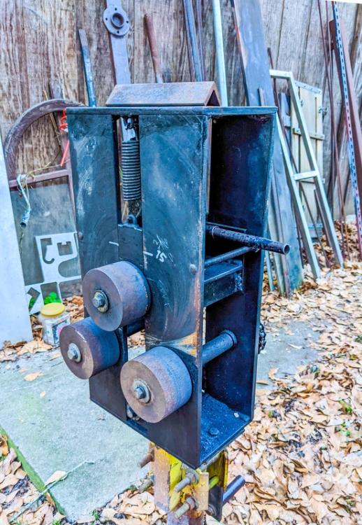
That is correct, they are not adjustable. However, in my next (?) similar project, I will definitely use your idea; the two bottom rolls are the drive rolls on this roller, driven by a hand crank and heavy sprocket chain on the other side of the machine. I can probably add the right size ring over each roller and use a keyway or countersunk bolt in each to maintain the transfer of crank power?
Great idea - Thanks
-
SOLVED ... for now. Thank you to all who responded!
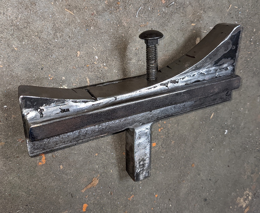
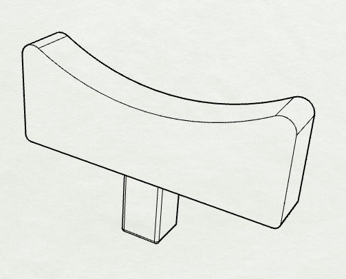
I just went ahead and made a rough but durable tool from scrap 1 inch thick steel to fit either a heavy vise or hardy hole. The radius varies from about 5-1/2 to 8 inches, and I treaded a hole for a removable bolt/stop at the "sweet spot" for this particular project. Seems to do a good job for now.

-
All the great input and ideas are appreciated, but in the interests of time (or more precisely, getting my procrastinating hind parts started on this big project) a simple curved cradle for the hardy hole will be employed for now.
I'll just hammer both ends of the flatbar into a nice 6-inch curve - assuming a little spring back - and see what happens. Not giving up the quest for something much more consistent though.
-
Thank you both, GeorgeN.M. and Glenn, those are both very good ideas, as my main target is consistency (reproduciable quality) first and time savings second. Obviously, material savings is important, too. I do pefer to work COLD in this project, so if Glenn's idea is used, I need to figure out the proper smaller radius for the tool if I go that route, due to the spring-back in bending that we are all familiar with. It is a 7-1/2 radius (15-inch diameter of course), so I'll see what happens with 6-inch radius tool to begin. Thanks!
-
On 2/22/2023 at 5:20 PM, George N. M. said:
Phillip, if it were me, if you are getting, say 2" of flats at the end when you are rolling, I'd just start with stock 4" longer and cut off the straight portions ...
Thanks, George. As noted above, I really need to economise on the material by getting five circles from each 20-foot length of flatbar; I cannot afford to cut off any excess, since each circle starts with a 47-1/4 inch length. May as well say 4 feet. Input definitely appreciated though.
On 2/24/2023 at 1:45 PM, Scott NC said:Notice the location of the rolls.
Thank you, Scott. My rollers are not configured like sliprolls are. That is, only ONE of the 3 rolls can be moved. Thus, there is simply no way to accomplish a smooth bend if the entire length of the workpiece (and no excess in length) is to be formed. In fact, the best this machine can do yields a 3-inch flat (see photos). Still working on it.
-
On 2/22/2023 at 1:54 PM, gewoon ik said:
With a good roller you can get hoops that are nice and round. You don't have to stop at the seam when they are almost there. You can continue and make those parts round as well
Are you saying to go ahead and weld the hoop together with the flats, then put it back onto the roller? I will give it go, but have doubts about my skills.
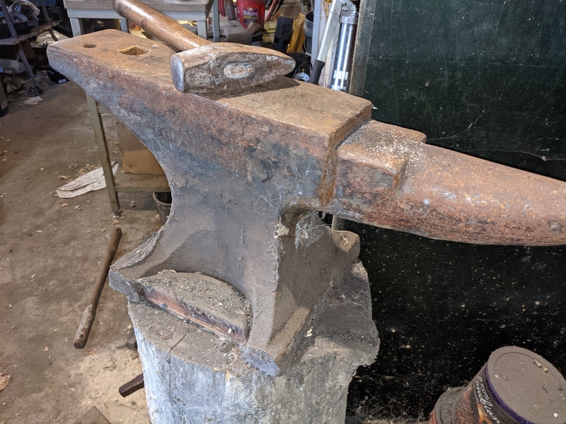
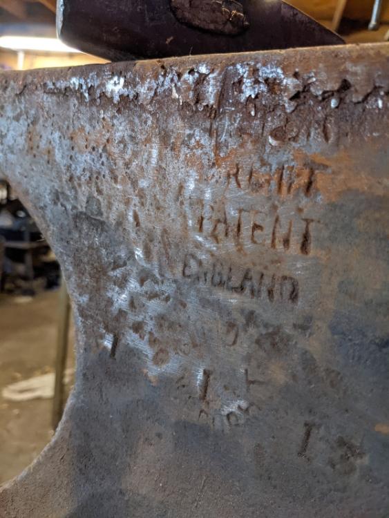
On 2/22/2023 at 1:56 PM, Glenn said:You bought the whole anvil, not just the face. Turn it on its side and use the curve between the feet, or under the horn or heel...
That is a stroke of genius for sure -- Thanks!
Those radii seem a bit small on my anvil though, like maybe for 8 inches diameter at most. It's just around 120 pounds (no clue of the actual brand (anybody?) or weight).
-
No doubt everyone on this forum is VERY familiar with the dreded flat spot created in large cold formed steel circles (and scrolls, too). On a short run basis, this is no big deal, since you can hammer a nice short curve in the ends of the flatbar or roundbar workpiece. But what if you are making a ZILLION (well, 90 anyway) CIRCLES??
I find myself needing to make over ninety 15-inch circles from 1-1/2" x 1/4" steel flatbar, and that is a good thing, but I would like to save time on the ends of my 47 inch workpieces if possible.
Has anyone here come up with a quick and consistent way of prebending the ends of what will become a hoop, that they would like to share?
I've tried pressing into a small curved space and that does not seem to be the ticket to success. I would be great to have a swage block with a large radius, using a quick hammer blow, but that isn't available.
Thanks for any solutions or hints to getting that curve onto the ends of the flatbar.
PLEASE NOTE: Often times the flat parts are simply made to overlap, and then the excess is trimmed away, BUT my workpiece is just under 4 feet in length and that allows 5 circles to be taken from a standard 20-foot "stick" of flatbar. Thus, using the trim technique would lead to a lot of wasted raw materials.
Thanks for any input!

-
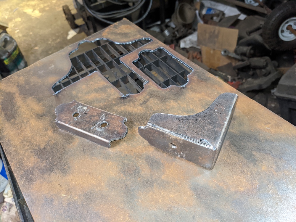
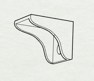
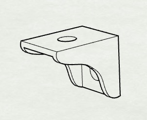
Thanks! Yes, they are 3 inches longways and accommodate 1-1/2 inch flatbar top rails. I did not go into specifics because of being dumbfounded -- in general -- that any such brackets are apparently impossible to find from suppliers. Still pretty much amazed at that.
-
Thanks again to all!
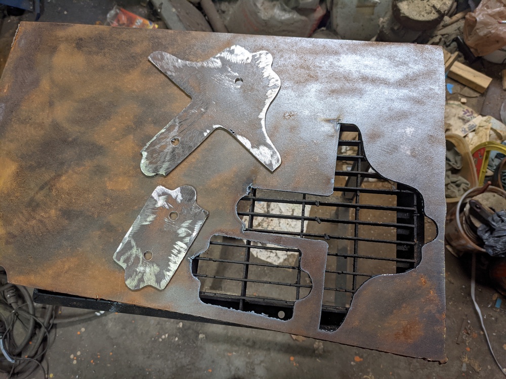
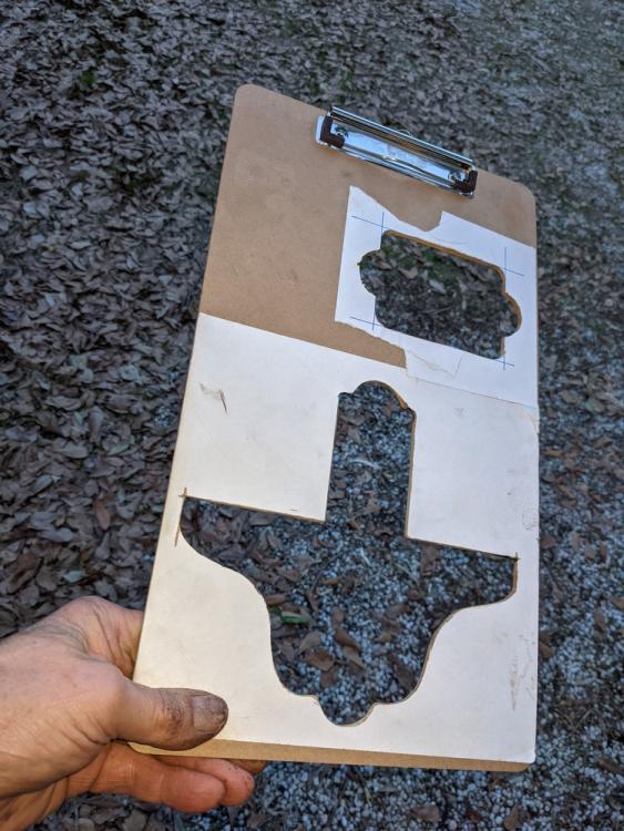
I went ahead with the pattern idea. Test pieces using 11 gauge turned out pretty well, so a little thicker will work. Note my fine "CNC" machine (masonite lasts a long time and 6 legal size clipboards are about 12USD)!

-
2 hours ago, anvil said:
The formula is half the thickness of the material added to each side of the bend.
Whoops! I goofed. You mean the material that will be bent into the part for the bracket. Duh. I got now. That material will be 1/8 inch thick sheet steel.. Thanks again.
-
47 minutes ago, anvil said:
Lol, A grinder will solve your fit problem there... However and modify the bend area with added material for a forged to dimension right angle bend. The formula is half the thickness of the material added to each side of the bend.
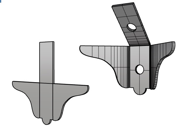
Thanks! Just to make sure the patterns are right, if the width of the top flatbar toprail (yes, I know channel top bars are the norm now, but this old fence is really OLD) is 1-1/2in and the thickness is about 3/16 or maybe 0.2 in with old paint, then the cutout finished blank should be wider?
Two side bends over the flatbar, so 1.5 + 0.1 + 0.1 = 1.7 if I understand it?
-
double reply - sorry -- see below
4 hours ago, anvil said:Lol, the Devil's in the details and this detail will prolly be the most expensive part of the job. I like Thomas's idea of starting with the proper sized channel.
On 2/2/2023 at 10:49 AM, ThomasPowers said:I'd start with channel iron the correct width.
Yes, channel would be GREAT... BUT (Mr. But always seems to show up) the flatbar to be inserted is 1-1/2in wide, and there is no standard of channel locally with that inside dimension. Dang it.
-
12 hours ago, JHCC said:
Another option would be to cut two pieces of angle iron to the inside width, sandwich them between two square pieces of plate, weld around the edges, cut the squares corner-to-corner, and grind smooth. ...
Yeah, pretty sure that or something very similar is what I will go ahead and do -- Thanks.
Simple is usually best ... yet again.

-
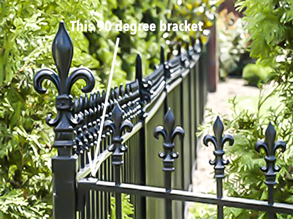
STILL gobsmacked and stunned that this is either rare or unavailable.
These are everywhere... on fences and rails. Not whining, but amazed. May be a small business opportunity for someone younger than myself.
-
12 hours ago, George N. M. said:
I don't have a fancy CAD machine but my first thought on how to make one is as follows: Start with a legth of thick walled square tubing ...
Thanks, George. That is a very good idea. Pretty much at my witt's end finding this very common bracket, so may go that way.
2 hours ago, NoGoodWithUsernames said:Hopefully this doesn't get cut for being a commercial site. Actually I just won't post the link. ...
Yep, the link worked. MUCH appreciated, that is EXACTLY the type of thing needed, but the size is way to small and it is the only one they offer. And it is aluminum, but that is okay.
-
Regarding making this myself, the pattern could be flattened and cut as a negative/hole out of masonite (old clipboard material is good). Then a bunch could be plasma cut from THICK sheet metal, then drilled, then bent into shape and welded.
Man, that is a lot of time ... and WORK (does anyone remember Maynard G. Krebbs?) These brackets have to be offered somewhere.
Thank you all again. Please keep the ideas coming.
-
Thank you ALL for your fast responses -- so much appreciated.
5 hours ago, 1forgeur said:Can you make one from square tubing?
Yes, I probably can, and that is a good idea if no supplier is located (at a reasonable cost, of course). Thanks.
4 hours ago, Anachronist58 said:I try not to swear, but I thought for sure that I saw these at Industrial Metal Supply last week...
What is the urgency level of your project?
That would be GREAT. I will definitely call IMS tomorrow.
Urgent -- like I have about three weeks for the whole job, which includes a lot of other stuff.
1 hour ago, George N. M. said:Phillip, have you CALLED Stewart Ironworks and asked them directly where they obtain their brackets? If not, do so. That may be the easiest solution for the problem. Or, as 1Forgeur suggested, they would be pretty easy to fabricate
Yes, a few times, but have been forced to leave a message at what seems to be a contractor's location. Then once, on the phone where the impression was given that the part was not available except on their custom work. I respect that.
-
Thank you, George, but NOPE. VERY Surprised, they do not. Considering these brackets are just about everywhere you see old fences and rails, it is amazing this part is not even mentioned at the suppliers. There is a place called Stewart Ironworks in Kentucky that actually seems to use these brackets on the custom fences, but they do not sell them or reveal a source at this time.
-
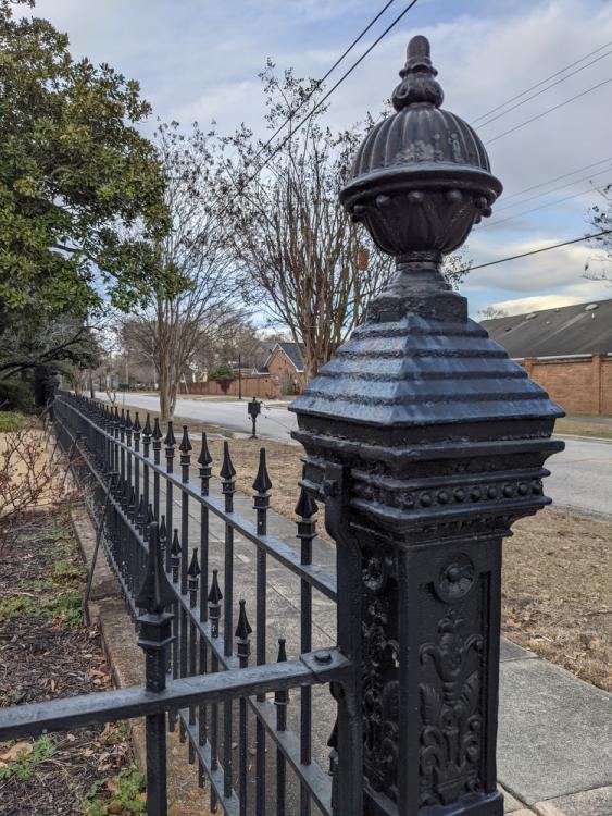
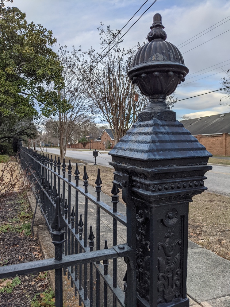
I am about to do some repairs on an old ornamental iron fence that has a number of missing brackets where the top rail connects to posts. It is missing about half of these (20 or so). I want to find something just similar to what remains on the fence, NOT simply use a bent metal tab.
These -- or anything like them -- appear to be impossible to find. These cast iron brackets are very common to see on old iron fences, but zero luck finding replacements.
Apologies for no photo, but here is a couple of images. I can make these, but surely someone offers these -- ANY help is appreciated!
THANKS!
-
I am fixing the forge walls, and will use kaowool inside with a coating as recommended. I have seen several of the really-high-heat refractory coatings but am really surprised at how expensive those are for just a small amount of material. Dang. Must have gold and diamonds and moon dust mixed in.
I will indeed try to melt a piece of steel when this is fixed up.
A thousand thanks.


COLD Pre-Bending the ends of rolled circles and hoops -- Ideas?
in Cold Worked Iron and Steel
Posted
Here is a photo... so far.
L-O-N-G way yet to go on this project.