bcrimmins
-
Posts
12 -
Joined
-
Last visited
-
Thank you, Buzzkill, that's really helpful feedback. I found some pictures of burner flames that match your description so I think I have a better idea now of what I should be striving for. Frosty, thanks for your detailed reply. I learned a lot. Your knowledge and experience of what seems like every aspect of every design factor is impressive. And thanks for helping me get to the movies on a Saturday night. As I understand it, these are the factors (alone and in combination) I can adjust. If you have any specific insights to any of them (or if I missed any), I'd be grateful for your thoughts. Air flow volume. Can't really increase this very much because the aperature of the T is fixed. Alternatively, I could drill some additional holes if more air volume was necessary. Orifice diameter. I'm using .030 mig tips. I could change that out for a smaller one if less gas with higher "stream pressure" is desirable. (I know "stream pressure" isn't a real term. :-) Orifice position. I can move this up and down. Based on Frosty's comment, I reckon I may need to shorten the mig tip to allow for a proper position. Gas pressure. Basically adjust the regulator up and down the pressure spectrum for any configuration I want to test. Nozzle alignment. I will smooth and straighten this out.
-
Thanks, BlueGoat. Yes, I did build the Frosty T burner as spec'd, with the exception of using a cross instead of a T so that I could add the threaded lamp pipe to allow for adjustment of the orifice position. As I've said, I'm a total noob to burners; but my judgment was that the Frosty design works great! The idea of adding the threaded pipe adjustment was just "fiddling" based on some of the conversation in this thread. The only reason I added the water putty was to mitigate a little bit of buffeting of the flame that was (as BuzzKill and stevomiller pointed out) probably due in part to the step down bushing that I added so that I could use the 1" cross. All in all, I would say that the added adjustment capabilities of the threaded lamp pipe are marginal at best. I couldn't detect much difference based on positioning the orifice up or down, except at the extremes -- everything between the extremes was pretty much the same. I think if I make another burner I'd forgo the threaded pipe and just use a T as Frosty's design calls for. I do, however, think that I will use the water putty to smooth out the air flow paths as that virtually eliminated all of the buffeting. Interestingly, smoothing out the ports in an intake manifold (where gas and air gets mixed) is also a common practice for increasing engine performance in muscle cars -- "port and polish", as it's called.
-
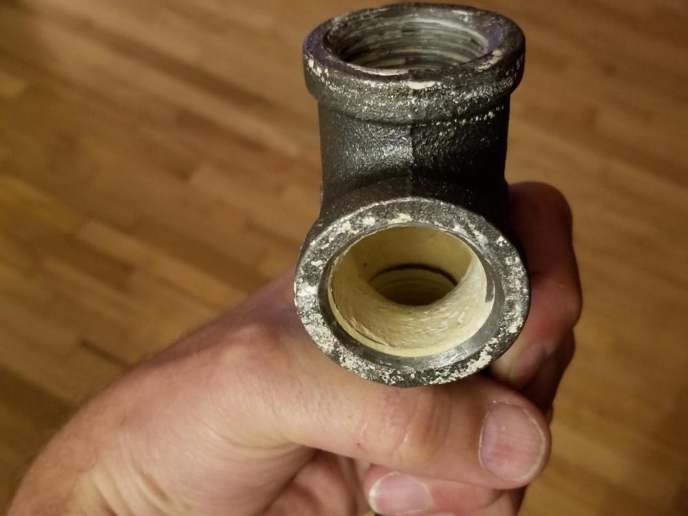
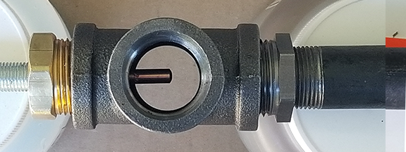
Hey guys, I think I've made some progress. The modified Frosty burner I showed in the previous post (with a cross and a lamp pipe) produced what I think is a much improved flame, i.e., almost all blue flame instead of the mostly yellow/orange flame and with a low roar instead of the whistle from the first iteration. It's also more compact. But it 'buffeted' rapidly... "pup pup... pup... pup pup... pup pup pup...." I think this is what Buzzkill and stevomiller were warning me might be an issue with turbulence generated by the reducer. I thought it about it a bit and instead of grinding/milling/drilling the thing, I decided to try smooth out the transition from the T through the reducer with some water putty. While I was at it, I all so smoothed out the threads leading into the T, since it seemed like the air flow coming into the T would need to travel across that 'washboard' texture. I also did the same for the flare reducer, eliminating all turbulence that could be caused by either the pipe-reducer transition, the threads at the exit hole and the internal concave profile of the reducer chamber. Here's what it looks like through the top of the T (cross). I still need to sand the watter putty a bit more to get a nice glassy-smooth finish. In the picture below, it looks like the water putty is pretty thick at the threads of the T intake holes. It's actually less than a millimeter thick, but I'll sand that down to the top of the threads to ensure max air flow. still need to sand the Here's the nozzle. I already sanded it down pretty good. And... the big reveal... here's the flame. I feel pretty good about it, but it's my first flame so I don't really know if it's very well "tuned". What do you guys think? Is it good? Is it good enough? In any case, THANK YOU for all your help. 2018-07-28 22.57.01.mp4
-
Roger that, on both counts. Cheers
-
Thanks, @Latticino I have the pipe tape covered. When you "gas rated", do you mean the quick connect? Or a different fitting? The rest are all just steel and brass.
-
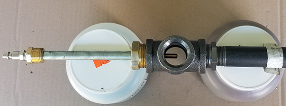
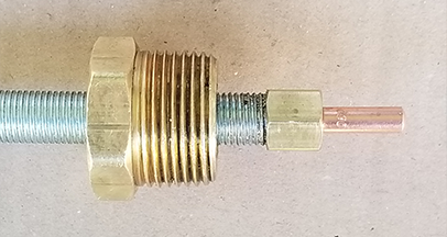
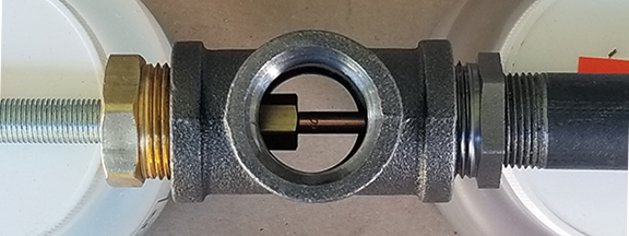
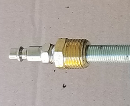
Gentlemen, thank you all for getting me straightened out. As I said, I am going to build the Frosty burner. However, Latticinos comment about tuning via orifice position got me to thinking. So I made a minor modification to Frosty's design such that the depth of the orifice can be readily varied for tuning. Here are some pics. Your critiques are welcome. The first image is a full length view of the burner. The body is a 1" cross. The Frosty calls for a 1" x 3/4" T. But by adding a 3/4 reducer bushing I can accommodate the 6" section of 3/4" pipe. Since the transition from 1" to 3/4" at the bushing adds a dimension step, I recognize that may add some additional turbulence to be accounted for. Is that correct? On the opposite arm of the cross, I use a brass 1" x 1/4" NPT reducer bushing, through which I twist a 1/2" threaded lamp tube. The lamp tube thread count (18) matches the NPT fitting , but the NPT fitting is tapered so I had to tap it with a straight 1/2-18 tap. The threads of the bushing also only went half way through the bushing so I used a step bit to open up the back end so that the lamp tube would pass freely through. To the end of the lamp tube is threaded a 1/4" NPT cap, tapped with a 6mm hole for the MIG tip. By turning the lamp tube, the position of the MIG tip can be moved in and out to different depths. Here you can the MIG tip in roughly the recommended position for the Frosty burner. Here you can see the tip is positioned below the air entrance port. I will trim the length of the lamp tube, since I reckon there is no need to attempt tuning the position deep inside the 6" pipe. Also not shown, I will add a lock nut to the lamp tube to ensure it doesn't move once tuned and a shutoff ball valve for convenience and saftey. I'm using a pneumatic hose coupler to connect to the Propane hose. Not sure that's a great idea. It doesn't leak at the moment, but I don't if the gas will have a corrosive effect on the o-ring over time. Once I get it lit, I'll share pics of the flame as well tuned as I can get it and based on the comments I've read about what makes a good flame. Cheers, Bob
-
Thanks, @Latticino I have cleaned up the post and will be careful. Thanks also for the thoughts RE orifice location and tuning. I will noodle on that.
-
@FrostyI have high respect for all of you and I would not think of copping an attitude. If you ever sense that I'm being an idiot, I assure you it's just the limits of language typed into a form without sufficient attention paid to word smithing. My "I'm feeling Frosty" comment just meant to say that I'm going to build your "KNOWN PROVEN EXCELLENT DESIGN", as Steve referred to it. It is indeed a simple design and one that I had run into in my initial search. At the time I started looking, I didn't realize that burner design was such a practical science; I thought you just had to shoot some gas down a pipe and light it up. Boy was I wrong. To be clear, I don't "prefer to experiment and reivent." I just want to build a forge and thought I had cobbled together a bunch of parts that would work. The burner I built seemed (to my uninitiated eye) to belch out such big fat flame and it seemed like it was too much flame to shove into a 5-gallon bucket. When I realized that, I posted her to check my suspicion that the burner I made was not good. Turns out it was not good, but for reasons I didn't even consider -- I thought the burner I built was too powerful... turns out it wasn't even a question of being too powerful... it was just a terrible burner, terrible flame, terrible design, terrible pretty much everything. To answer your question of "why ask us if we think yours are right", I just wanted to see if I could use what I had learned to salvage what I had already bought... and tapped... and drilled. But I see from Steve that that's pretty much folly. So I'm reformed. I'm going to build your T burner to get my first furnace built. It's just as likely as not that every future furnace I build will use the same design. As I said before, I didn't realize that the parameters for burner design were so precise and specific. I'll focus my inventor energy on the art I will make from what gets melted in the forge and gratefully leverage the great work you guys have done to work out efficient burner design. Thanks.
-
Thanks @Irondragon Forge & Clay. I hadn't. But, you're right, I should have. And now I did. Thanks, @stevomiller. I know you're right. I have a disease: I always want to try to figure stuff out on my own. But your advice is spot on -- best to make one that works well first (so I can make progress on the project I'm working on) and then use that as a launch pad for possibly tweaking and making it my own. This is especially salient advice given that my objective is not to become a bad ass forge builder but, rather, to melt stuff and create art from it. I'm feeling frosty.
-
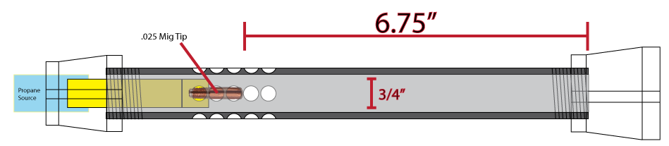
Ok, after reading a bunch I came up with a new configuration. I would be grateful for any feedback. I think the dimension are reasonably close but I'll mess with tuning if it works even half-way well. The biggest uncertainty in my mind is the air intake holes. I'm thinking 20 holes, four opposing rows of five holes. Each hole is .3 inches. I would add a choke sleeve to control the volume of air. Switching the 1/16" drilled hole in the brass cap for a .025 mig tip.
-
Thanks stevomiller and Buzzkill. I actually started with the Burners 101 thread. But I see now that I didn't give it a chance. When I first saw that is was 48 pages of posts, and the first half of the first page of posts included a lot of chit chat, I figured it was a great idea (i.e., a consolidated and focused treatment of information on burner theory and design) that devolved quickly. So I didn't read any further. At your suggestions, I went back and gave it another chance. Glad I did. I'm learning a lot and will continue to read the posts. Once I have a better foundation (and perhaps a better operating burner) then I'll pop back in here. Thanks, Bob
-
Greetings. Working on my first forge. It's a 5-gallon bucket design. I borrowed elements from a few different designs and ended up building a monster burner -- at least I think it's a monster. I'm worried that it's way too much flame to dump into the 375 cubic inch cavity of the forge. Here's a link to a video clip of the burner on it's first firing. Granted, it's the first time I've see one of these things in action so maybe it's not as aggressive as I think it is. The specs are: 24 inches of 3/4" steel pipe with a 3/4" to 1" reducer fitting on the end. 30psi Propane regulator (in the video it's at about 75% of that.) The Propane orifice is a 1/16" hole drilled into a brass fitting. (I wonder if that's too big?) Naturally aspirated with ten, 1/4" holes drilled in the pipe. https://www.dropbox.com/s/kixcnfdlxgj6rl0/20180715_134019-c.mpg?dl=0 Is this sucker too much?