

carlson
-
Posts
66 -
Joined
-
Last visited
Content Type
Profiles
Forums
Articles
Gallery
Downloads
Events
Posts posted by carlson
-
-
Thanks for the replies.
What kind of Wolf jaw tongs do you use Frosty?
-
As a beginner with a limited budget I'm tempted to buy offset (gooseneck) v-bit tongs. They "seem" to offer the greatest versatility.
I'm specifically looking at the Off-Center brand offered by Blacksmiths Depot.
Is there a downside over the inline pair?
Thanks.
-
If nothing else, I can imagine a one-off porcupine sculpture. Maybe wood body covered in stainless steel quills.
Heat up the tips in your forge or with a torch and then burn them into the wood. Or pre drill and glue.
One off in that you could put it in your office. If your confident in your sterilization methods maybe you could sell them or give them away.
-
Are those stainless washers or galvanized?
-
Is each tooth a single piece bent in half and slid over the central piece?
-
Maybe not efficient as the previous methods, but I could see getting the arcs from slicing thin sections of pipe and the cutting the slice in half or thirds.
Would probably only make sense if you had a band saw or big cutoff saw.
-
Two of these would be great for picking up 8 lb pork butts after smoking them.
-
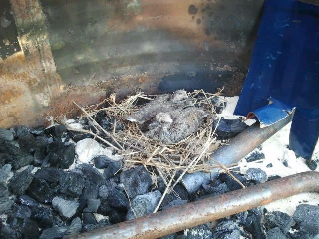
Some morning doves a while back when I kept my forge in the backyard instead of the garage.
-
Compared to a lot of forums, IFI doesn't have as many new threads. A 5 year old thread could easily be on the second page. Plus I imagine very few people worry about checking the date.
I use forums as a source of information and ideas. I'd say from that perspective having the same information presented from multiple view points is value added.
-
Needs a hardy shank

-
Did you make them straight then bend the bit? Maybe with a piece of the target stock in the bit?
-
On a related note, what would be the safest way to make the cuts for a split cross using a portaband. Feels like the fingers are awfully close with 1/2 inch stock.
-
I find it rather interesting that on this blacksmithing site, and two pages of replies, only 3 suggest hot cutting with forge and anvil.
Hot cutting is a new fangled invention by blacksmiths to lazy to pound the stock into the shape you want. Humbug!
-
My brother-in-law says he can do the 9" portion of 1 3/4" at his work. I'm still going to explore the VoTech angle. May end up with a hybrid machining/forging approach.
I appreciate any tips/tricks I can get...theoretical or otherwise.
-
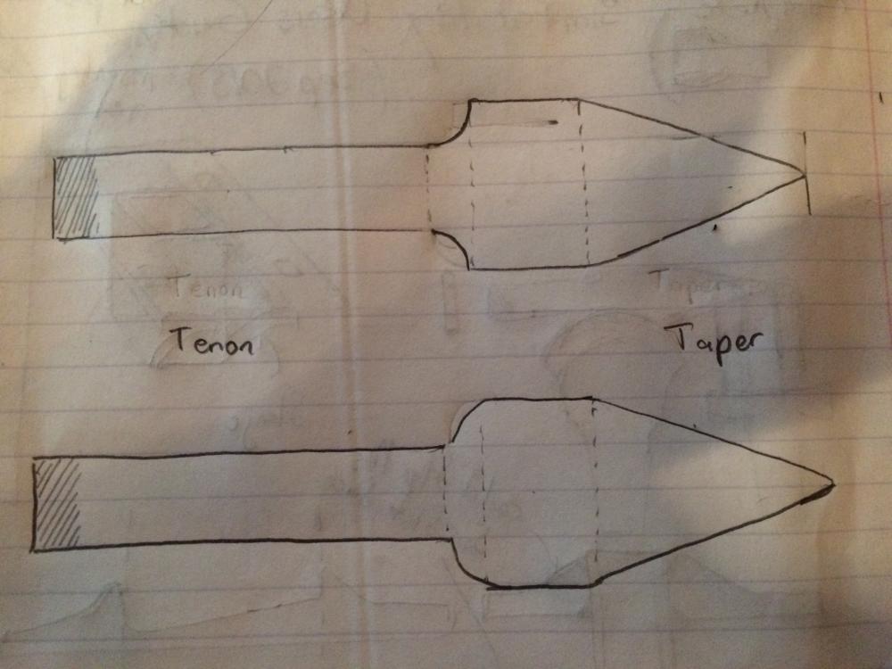
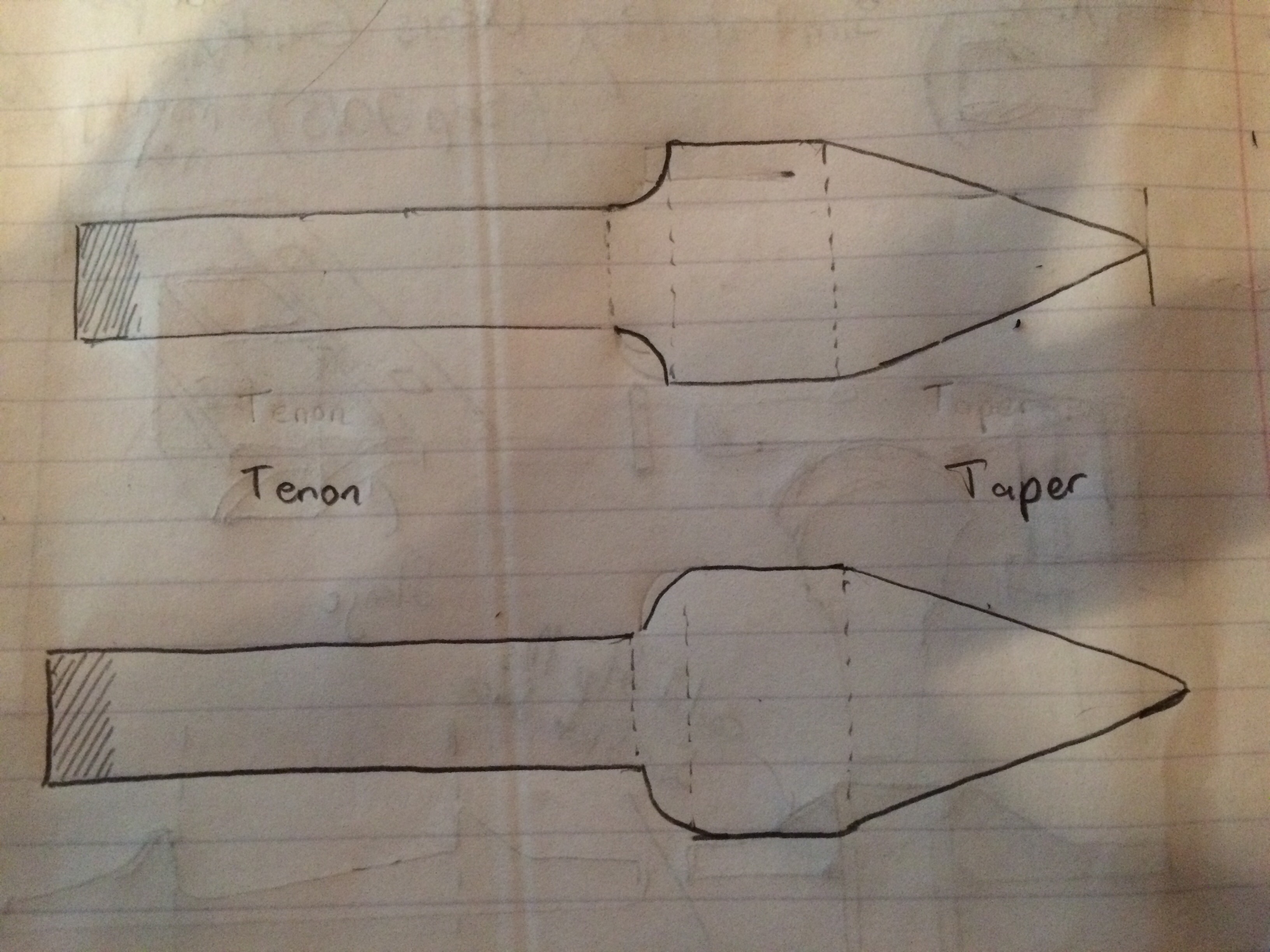
I was mostly just joking about peining it like a tenon though it'd work fie. Were I doing it I'd trim it so there's maybe 1/2-3/4" protruding, chamfer and weld it. 9" isn't so long for a horn, I was thinking the knuckle was narrower for some reason and the pics you posted show the relation clearly.
Frosty The Lucky.
Would a mig welder be capable of performing this weld. My brother-in-law does welding for a living and fun.
Would you weld the cone side as well?
-
Ask the Votech to turn the cone on one end W/ shoulder, turn the other to fit the coupler snugly and thread it for a lock nut.
Frosty The Lucky.
Frosty
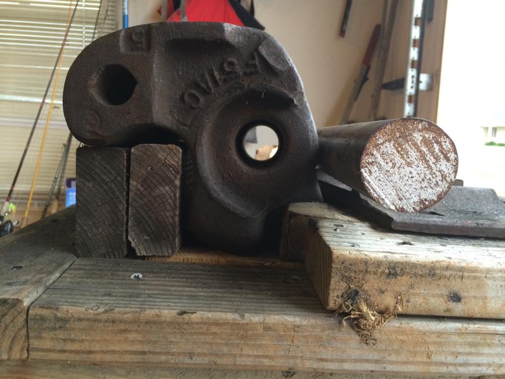
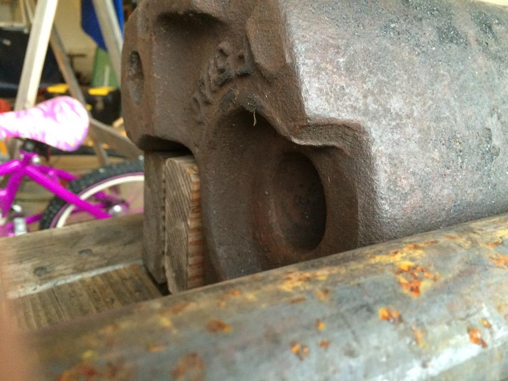
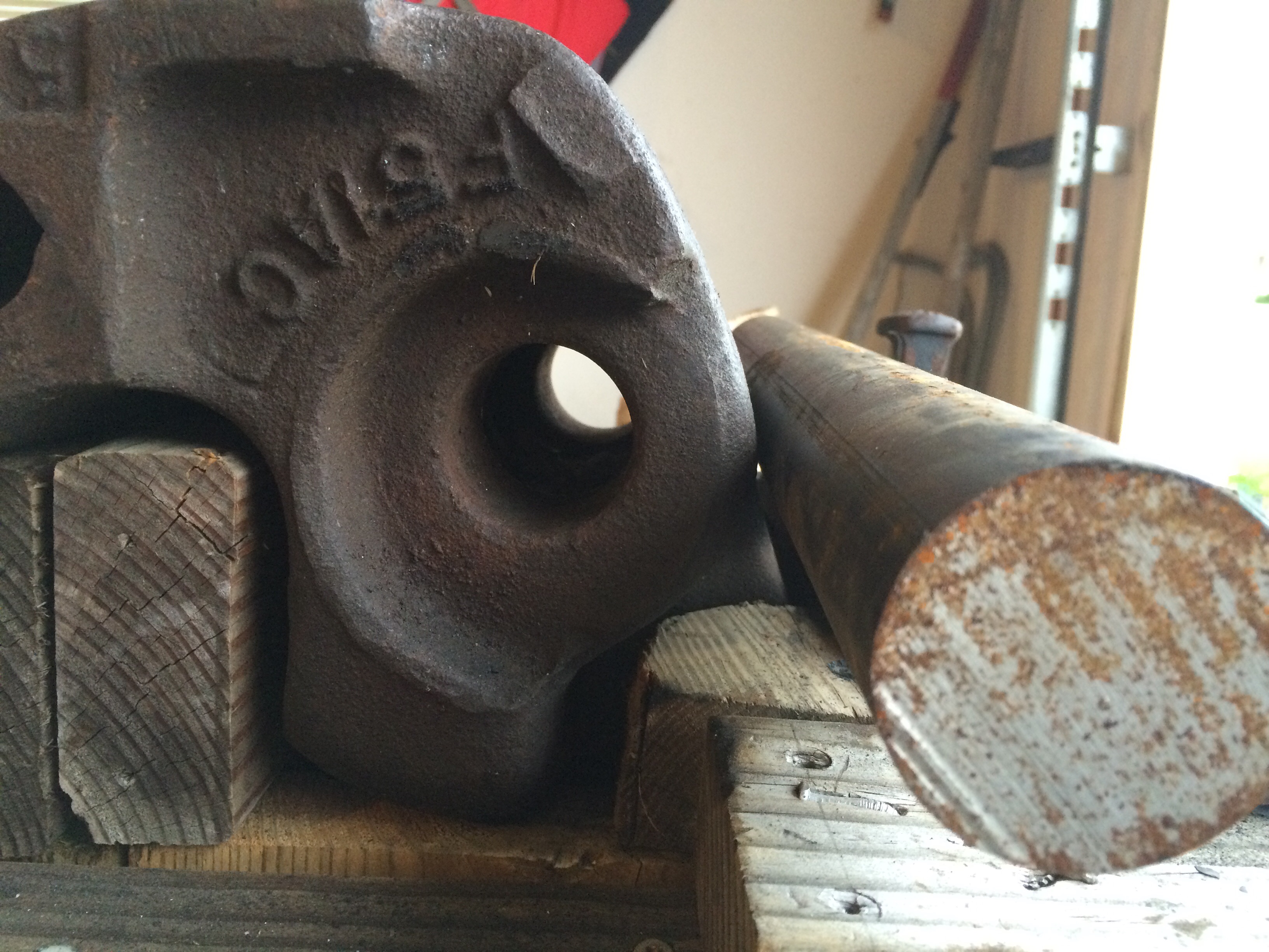
Is either of these transitions at the back of the horn section what you were referring to when you say shoulder?
Also if I'm able to get it machined would I want to find a bolt before hand or just provide some spec for the threaded end.
Thanks
-
Charles: I think once the tenon is swaged to fit the hole he should just pein it over. Just think how tight it'd be once it cooled.
Frosty The Lucky.
I seems to me expansion would be most drastic along the length of the bar but do you think it would be an issue in pushing the tenon through the hole.
Do you know if this part is cast and whether there's a potential of cracking it if it cools to tight.
-
Thomas and Frosty
I think given the 8 inches through the body of the coupler + maybe an inch of overhanging material on the working end leaves me 9 inches of material I need to shape.
If I go the machining route I the length won't change. How would you suggest breaking down the remainder.
Meaning how much of an end should I leave in the back to peen. What kind of slope/taper should I have.
how small should the tip be for working small objects like bottle openers and hooks without being a hazard to get impaled on.
Thanks for your help. Sorry for the flood of questions.
-
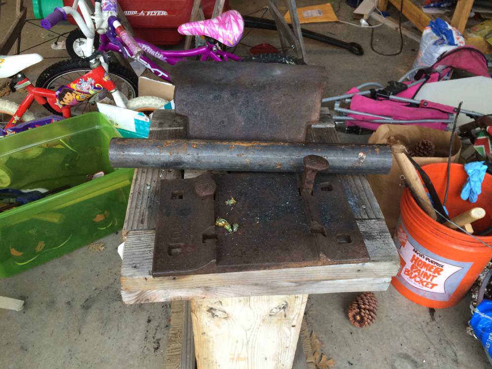
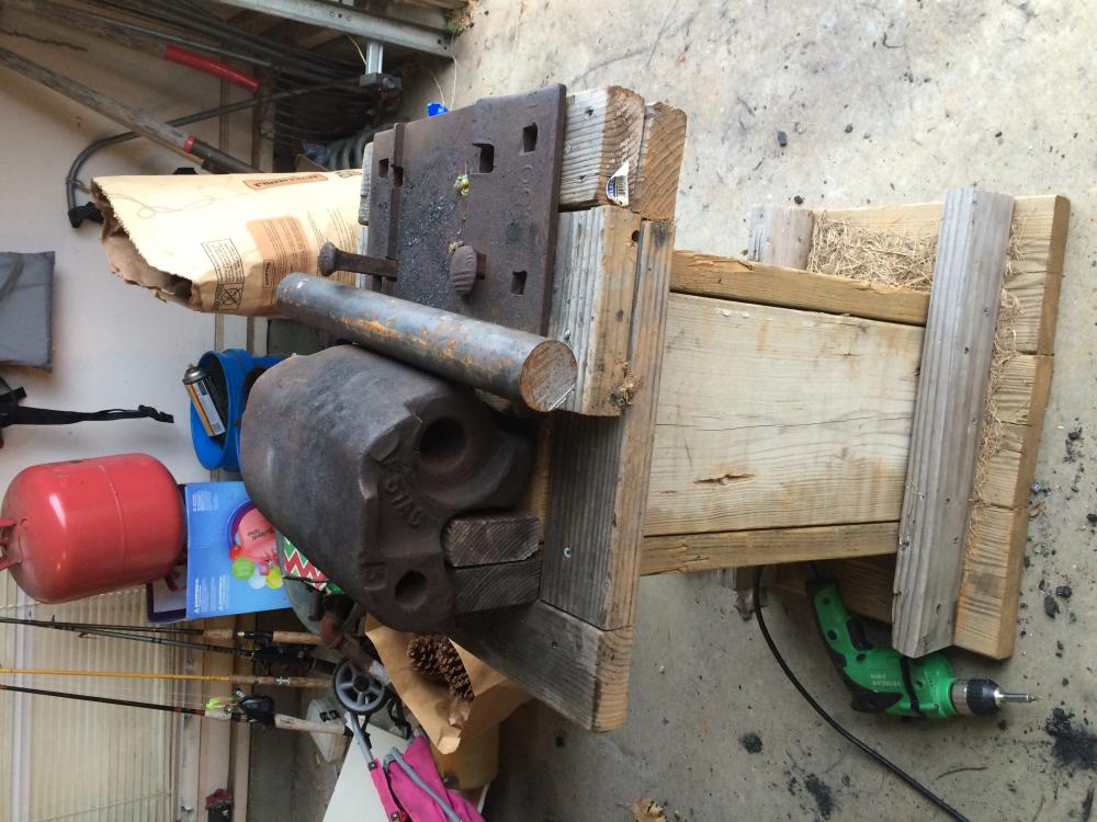
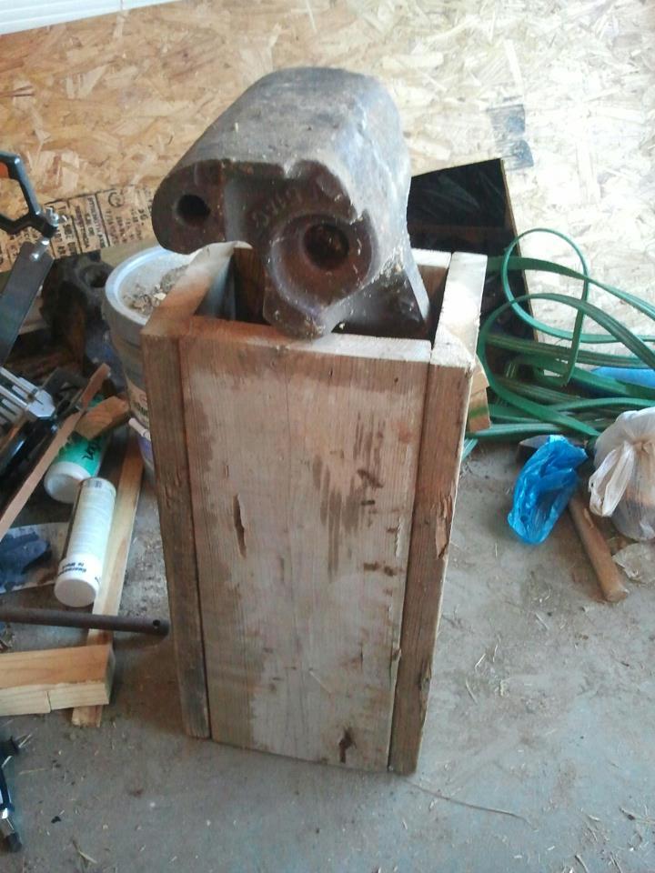
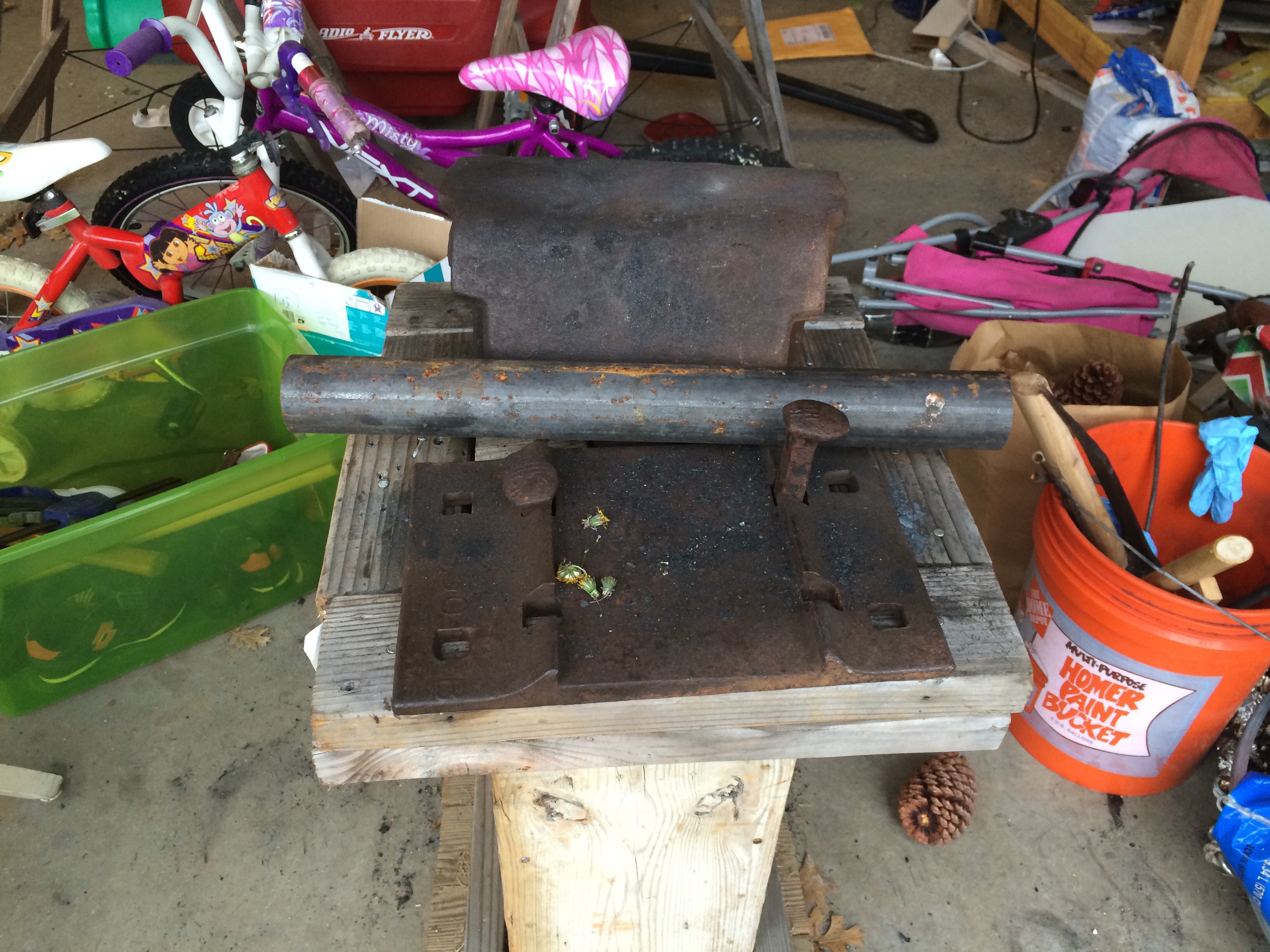
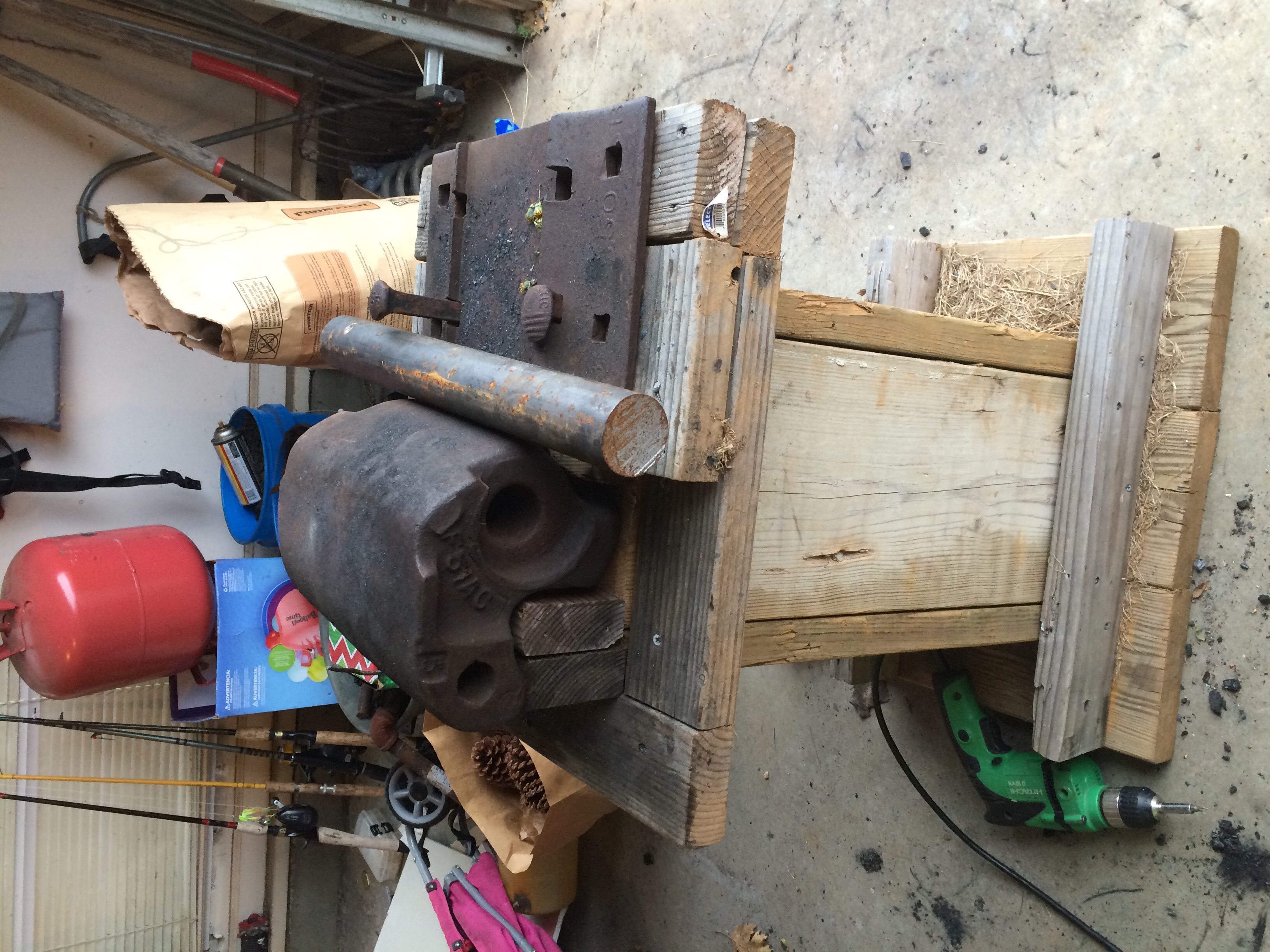
Better pictures
-
Nice coupler by the way! Excellent substitute for an anvil. I looked into acquiring one of these back when I got started and the restoration railroad enthusiasts were aghast at the idea of using such a precious bit of necessary equipment to pound on.
Well if a restoration railroad enthusiast were to allegedly find an anvil half buried by the side of a railroad track I would theoretically definitely be willing to swap.
Then I could try to come up with an even dumber idea on what to do with this lump of steel.
-
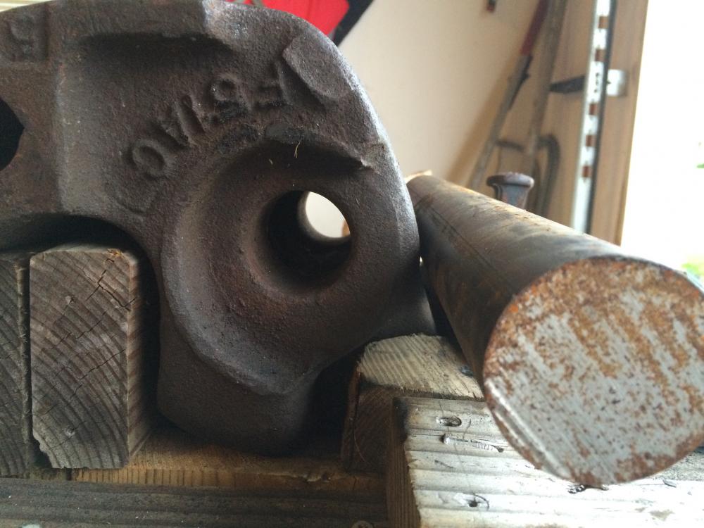
I bought a piece of 2" x 18" long hot rolled mild steel rod to use create a horn for my railcar coupler anvil. The attached picture was an earlier picture before I finished up the stand.
The bigger hole in the coupler is approx 1 3/4". The length the hole passes through the coupler is 8".
Being hot rolled my understanding is that the rod will likely be a bit over 2" OD.
So I'm looking for suggestions on what the best way of getting a horn shaped and mounted in the coupler.
I'm mainly going to use the thick portion for working on hooks and things like that. The cone portion for bottle openers and opening up curves that got closed up to much.
1.) Shaping the horn.
I imagine a day with an angle grinder and a stack of grinding wheels and flap disk might create the cone section. I'd be losing material that way though.
I might be able to get some help from one of the professional smiths and a power hammer at our forge meetings. I wouldn't be losing material that way.
This is a cheap-o project (other than time) but just to throw it out there how long would it take someone in a machine shot with a metal lathe to kick something like that out and would it be prohibitively expensive?
2.) Reducing portion passing through coupler.
Again always have the grinding wheel options.
To reduce on a power hammer do you have to have a sizing block to stop the hammer at the desired size? Does this sort of operation lend itself to having an end product that would slide into a set size hole or am I asking for a level of precision thats unrealistic.
3.) Mounting to coupler.
Should I just forget about grinding down the pass through portion and just strap it down beside the railroad coupler?
Leave it loose-ish just slid into the hole?
Use some sort of caulk. I seem to recall posts about Brian Brazeal's thick plate anvils getting mounted using some sort of silicon caulk. I would imagine epoxy would be too brittle.
Have an inch or so extra out the other end, heat up, and peen over like a big honkin rivet?
Thanks in advance for your help.
I can get better pictures of everything when I get home tonight.
-
It's obviously to late for Spanky's event but someone could glue neodymium magnets into holes drilled into the backside of the wood.
Would stop someone from making off with a piece though. Unless you used really strong magnets.
-
What if you got 6-12 inches of metal tubing just big enough for you stock to slide through and cut out a pencil/marker size slot down the length of it. That would let you get a straight line.
-
Now you gotta move a 750 lb treadle hammer


Downside to Offset V-bit Tongs?
in Tools, general discussion
Posted
I was hoping he had a source for Dire Wolf Jaw tongs.