RyanMark
Members
-
Joined
-
Last visited
Everything posted by RyanMark
-
-
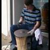
I thought you all might like to see this. It's a casting made from tin-bronze, and I've been working it cold. It's been through two annealings so far and will probably get a few more, then I'm going to lathe it. This is my first cymbal made this way, and maybe my third or fourth cymbal total.
-
They can cut the 4140 Q and T. They can't do anything harder. I used the term "pre-heat-treated" just to make sure they knew what I was talking about. I probably won't get the gears further hardened.
-
Thank you, Ric. I thought the engineer was coming up this weekend but it's actually Fri the 11th. I'm not buying any steel until I consult with him first. I won't have any extra money til then anyways. Related: With my theoretical force plugged in, Martin said gears made of 4140 HT with a 3" face will work.. On the other hand if I went with 1144 or similar, I would be looking at a 20-inch tooth face! wow
-
The channel beams are thick but the short, tapered sides don't work with my design. Bar channel has parallel sides but can't find in in large dimensions. So I'm looking at flat bar which I found in a variety of thickness/width
-
I thought I was limited but it was just my ignorant self, not knowing what to search for. I can construct it out of flat bar, rather than "plate".
-
Well, besides two huge thick-walled castings, how would one construct a frame out of metal so thick? Is it possible to weld such thick steel plate? By wrought, you mean that it's been processed after casting, not necessarily wrought into shape after purchasing the stock, correct? I couldn't find any angle or channel (with parallel sides, 6" wide) thicker than 1/2".
-
What about the frame,now? I was thinking 1/2" mild steel plate/channel/beam combination, welded together and to a 1" thick plate for the base. I don't know how much it would cost, but would casting the two main parts of the frame (left and right "pillars") and then weld them together and to a base be better? I haven't looked into the cost of iron/steel casting, but there are a couple of foundries nearby. By the way: It looks like neither stock gears nor old tractor bull gears will probably handle the force (assuming I can produce that force), according to the nice people at Martin who plugged the numbers into some software. So, I plan on having them fabricated from alloy steel.
-
Thanks again, Ric! I appreciate your time and input. This bronze doesn't like to be reducted too much anyways or it will start to crack. Which reminds me: Is there a relationship between the shape of a material's edge and the ability to be drawn without cracking? Someone told me that of two shapes, a circle and a square, that the circle will be the shape most likely to split at the edge when drawn out. I know a mechanical engineer who designs wings for Boeing. He's coming up from Wichita next weekend to visit some friends here in KC and he's told our mutual friend that he would love to see what I'm trying to do and help me out with it. It's not his specialty but maybe he has some more advice.
-
I've decided to make a 4-hi mill. 16.5" working width. 8.25" diameter hardened 1045 backup rolls (my stock wasn't quite 8.5" but I kinda knew that). 3.25" diameter work rolls: 4140 prehard with suface hardening, chrome plated. Or D2, whichever is less expensive in the end. This design calls for only the bottom work roll to be driven directly by the last sprocket (a Martin 100F70) and disregarding torque for the time being, I'm worried about slippage. What do you all think about a 4-Hi doing cold rolling with only the bottom work roll driven? No gears. If it matters, the bearings for the work rolls will only have to deal with rotation and keeping the rolls in place. The seperating force will be handled by the backup rolls' bearings, which are less than the 2/3 ratio mentioned. Backup roll journals are 4" diameter by 5.25" wide, bearings are C954 aluminum bronze 1/4" thick bushings inside steel blocks.
-
Me neither, I guess...lol.
-
Ric, I sent you a PM. Sounds like I should plan on adding that extra reduction stage. It could get me up to 4500 ft-lbs. The max working load for size 100 roller chain is over 5,000 lbs so I should be good. Worried about bearings again but too late. As far as gears, I was about to pull the trigger on a pair of Martin C540's but besides them maybe not being strong enough, I think my plan to operate them a few hundreths of an inch outside the correct pitch diameter might be stupid, especially for my application. How is the best way to put a pair of idler gears on an adjustable plane?
-
I think I found suitable gears on ebay, a pair of spur gears with the right outer and pitch diamters. I'd be varying the center distance by 1/4" which is going to create backlash and put much stress on the teeth, but I rather not have idler gears if I don't have to. Transferring motion to the other roll is more like an "assist", the way I see it. I'm just making it's friction work for me instead of against me, so I don't think the forces on the gears will be as great as will be on the sprockets on the primary drive side. So you think someone could weld a piece of 1-7/8" keyed shaft to the ends of the rolls? That's the bore of the gears. I'm guessing it should be done before any heat treating? I read that welding carbon steel requires a preheat and slow cool.
-
This will be manually powered by turning a huge wheel (the side from a large ditching spool) so all I have to worry about is the momentum of the rollers. I don't plan on touching them with my hands, and I'll lock the wheel when not in use. Hopefully the rolls won't fail, they're the most expensive parts. The sleeve bearings are meant to be worn, to protect the rolls and the bearing blocks. In the drive, I would think that the roller chain will fail before a shaft or sprocket...I might get the teeth hardened, though. A guard will be in order for the chain. And, I think bolting on gears could work. Actually, I just bought the roll material this afternoon. It's the 8.5" 1045 drop that the machine shop had from a recent job.
-
I've actually already ordered the bearings, cause I like to put the cart before the horse, haha... They're C954 aluminum bronze sleeve bearings which will slide into bearing blocks that are smaller than the diameter of the rolls, thus I can close the gap all the way. The frame and gap adjustment screws have been pretty much designed already. The rolls' journals will be 4" diamter and 5.5" long. A little small for the application but the largest I can fit into the frame (built with the largest angle and channel steel I can get). It sounds like I'm getting a great price quote on a 62" long drop of 8.5" 1045 but that doesn't leave room for gears to drive the other roll. It would be nice to not have to drive that roll...
-
Thanks. Stiffer is better for me, and If the mill works fine then I might hard-chrome plate the rolls for extra hardness and corrosion protection. I think I'll get another quote (they're going to get tired of me calling, haha...but they'll be happy when I buy). 8.5" is still a tight enough curvature to allow for reduction down to half a millimeter, from what I read somewhere. Another question: Do you guys think I need to drive the other roll? I would like to leave the adjustable roll non-driven for simplicity and less cost. The only mills I've seen that have a single driven roll are the Mcdonald mills. I will probably leave a few inches extra on both rolls for room to attach gears. I might have to push/pull my sheets through. Big gears are expensive! Ryan Jeremy- Power might be an issue, but I will have room on the frame for another reduction stage. At that point, I'd be looking at getting 3phase service hooked up and find a motor.
-
If I wanted to build a large rolling mill, which roll would bend less, given a 16" length and a force applied to the center: 6.5" diameter 4140 heat treated or, 8.5" diameter 1045. Both would be surface hardened. This is for cold rolling of bronze. Tool steel is too expensive. Thanks!
-
Actually, it wasn't so much being thin, as it was that I ground off the cast surface. The material is cast bronze...
-
Ok, I have a HF wheel and it wouldn't bend the plate, just flexed the frame. It wouldn't even bend it when I ground the plate down to 1/8" inch. However, I discovered that when it's already less than 1/8" thick, it shapes well with a hammer (cold). When it was thicker, it kept cracking when I tried to hammer it out, especiall hot. I'll use my wheel for straightening, it should work for that. Thanks everyone
-
Thanks Thomas, I want larger grains so that the material is softer, so I suppose I need to keep it dull red for at least a few minutes. I know that "recovery" happens all at once if there is enough energy stored in the dislocations. Today, I hammered a bronze plate (~17% tin), with a med-light force, and them annealed it, and re-hammered it. I made noticeable dents and bends in the plate, and a very slight reduction in thickness, but no cracks so far. Good sign!
-
Ok, thanks. I figure I'll do it anyways so I don't have to wait for it to cool.
-
Does bronze (specifically tin bronze) need to be quenched after annealing (to soften it)? I've read many times that it does, but this seems to contradict that copper and bronze can only be hardened by cold working. Would heating and letting air-cool leave the bronze workable, just as with quenching? From what I understand, it's the heat that's relieving the stress, so I'm wondering what effect quenching has on the microstructure. Thanks!
-
I have to try...no other options. I plan on doing plenty of annealing!
-
Just a theoretical question, assuming I had lots of time: What combination of bending and straightening would be best for reducing the thickness of a square foot of 3/16" plate, using only an English wheel? The sole purpose being to get it as thin as possible while increasing the width and length evenly...ending up as sheet. I have flat and radiused anvils for my wheel. Thanks!
-
right, thanks