
D33PAM
-
Posts
10 -
Joined
-
Last visited
Content Type
Profiles
Forums
Articles
Gallery
Downloads
Events
Posts posted by D33PAM
-
-
I need to harden and temper carbon steel on induction furnace.
The one i have is high frequency induction transformer.
The coil i made for it doesnt work and gets tripped indicating high frequency.
what is the diff. b/w medium fr. and high fr. inductions ?
and why does it trips ? -
On 8/7/2016 at 2:11 PM, Alan Evans said:
Do you wish to align the facets of the hexagon socket with the axis of the bar in the same position each time or happy for it to be random?
Can you use the external surface of the socket in a 90˚ bending jig or would it be best to be able to align the hexagon flats or corners?
If the drilling jig supported the socket on its shoulder and a drill guide was used inside, a slight variation in the bend angle would not affect the hole direction. It would still be in line with the axis of the socket.
Alan
Well i am currently working on the jig fixtures. since i am new to this its taking me some time to make them. It would have been really a great help if i would have seen a similar jig just to get an idea .
I can use the external surface of the socket in a 90 degrees bending jig. Can u please explain this process in detail ?
Thank You -
On 8/5/2016 at 8:35 PM, SmoothBore said:
I think the bend needs to be a 2 step process.
The first step would be to make the bend by the process you are now using.
The second step would be to fit the "socket" onto a hex pin mounted in the ram of a press, and "tighten" the bend by applying pressure, while the "handle" portion of the tool is supported in a simple female fixture.
I envision the fixture as a simple "slot", that will accept the diameter of the rod at the bend point ... with perhaps a properly located block with a female "hole", sized to accept the "straight socket" at the other end of the tool.
( This "hole" serves only to prevent the part from "rotating" around the axis of the bend, while being pressed. )
By then pressing the ram straight down, ... while the other end of the part is trapped in the female "hole", the bend is effectively compressed, while maintaining the 90 degree orientation.
A "center punch" point, ground into the end of the hex shaped ram, would create a centered "dimple" inside the socket, that will aid in drilling the clearance hole on center.
Lacking an arbor press, the same process could be duplicated in a large vise, ... but would require a somewhat more sophisticated fixture, to insure a 90 degree orientation.
i may be able to picturize in my mind what you are telling.
Thank you for assisting. i may text you again in case i require further assistance.On 8/5/2016 at 8:58 PM, jeremy k said:Induction heater for the isolated heat of the bend area so as not to distort the socket from heating and bending, This should be a fairly easy bending application.
Using Induction heating, the problem arises due to inaccurate bending technique.
On 8/5/2016 at 9:09 PM, ianinsa said:Are you quenching /cooling the socket portion prior to bending?
No, no hardening/tempering/quenching process is done.
On 8/6/2016 at 0:09 AM, rockstar.esq said:It sounds like you're drilling a bolt hole through the back of the socket. If so, maybe you could bump up the stock at the bend to forge a square corner which would give a good place to register your drilling and it would provide more material at the weakest point of the drilled hole.
Looks like you are familiar with the product. i may be texting you later in case i am stuck at any step .Thanks for your help.
On 8/6/2016 at 0:29 AM, Kozzy said:1 pc or 10,000?
Off the top of my head, I'd build a rigid sleeve for the shaft portion and push the bend from the outside of the radius. This is more akin to how one would put the bend on the end of a rod in a forming press. However, I don't know the specific finished part requirements and little missing details can make huge differences.
So basically i need to try and push the bend from outside ? i am familiar with forming presses and might have and idea of what you say.
Thank YouOn 8/6/2016 at 0:29 AM, Kozzy said:1 pc or 10,000?
Off the top of my head, I'd build a rigid sleeve for the shaft portion and push the bend from the outside of the radius. This is more akin to how one would put the bend on the end of a rod in a forming press. However, I don't know the specific finished part requirements and little missing details can make huge differences.
and this will be produced in higher amounts if successfully developed.
On 8/6/2016 at 3:11 AM, Frosty said:I see a closed die forging for a production run or a challenging hobby for a few pieces.
Make blanks, bend as needed and drop in the die the press or forge hammer upsets the socket end to final OD while forging the socket after which the final punch drives the hole through the angle, die rises part drops in a bin for final heat treatment and finishing while next blank drops into the dies.
With an experienced operator I'd estimate between 20-45 per minute for this operation.
The only real question about producing this tool being, is there enough market to support the plant necessary to make it worth making? With the right tools a single man operation could maybe make 10/hr. I figure the above estimate would take a 4-5 man plant. A CNC plant will take your customers really quickly if there's a decent market.
Frosty The Lucky.
Yes it is the process we use.
Forging part is done.The problem occurs in the bending part. Since i need high precision.
And its a risk we have to take by spending some time and exploring the market.On 8/7/2016 at 11:01 AM, gote said:Would it be too weak if you cut and weld or is it a customer's requirement to bend?
Welding would not do the job .
But Thank you for your help. -
58 minutes ago, Alan Evans said:
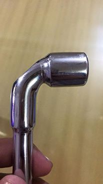
Your first images did not show that it was a socket, you knew it but I did not, which is why I described it as the larger diameter section!
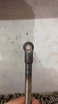
If you are induction heating and then bending by hand you need to align whatever you are using to hold the socket. As far as I can see from your later photos it is the socket that is off line not just the through hole. It looks like you have located the socket on a hexagon and then pulled the bar over to form the bend, but then twisted it clockwise so it is a compound bend and the socket head is out of line. Or you have pulled it down diagonally.
For the drilling, if it is important for the function of the tool for the hole to be in the centre line of the socket then I would make a drill guide with a hexagonal exterior to fit into the socket and drill through that. Provided you have pulled the bar down in a straight line it will come through the centre of the bend.
My Tee weld suggestion was based on the external appearance before learning that it was a socket and needed the through hole.
As far as the wasting/waisting of the outside of the bend goes, I referred to a larger radius not a different angle, but I can see that may not be appropriate now.
I have not played with induction...but are you able to create a coil which would heat a longer length on one side of the bar, and then use the longer heat length on the inside of the bend in order that the metal thickens there rather than stretches on the outside of the bend? Easy with a gas torch.
Alan
So is your difficulty not the stretching/thinning of the metal on the out side of the bend as I supposed, but rather being able to achieve 90˚ accurately?
Or is it the offset of the socket to the bar?
Alan
i understood drilling part very well Thank your Sir.
As far as bending is concerned..the priority goes as
- Accurate right angle bend
- Socket offset ( which might be corrected if right angle is obtained )
- Thinning (minor lessening in dia. can be compensated ) -
2 minutes ago, Buzzkill said:
Could you clarify this? You didn't really define what the problem is as you see it, and for me at least that makes it difficult to suggest a solution.
i am unable to make a 90 degrees bend that is my problem.
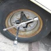
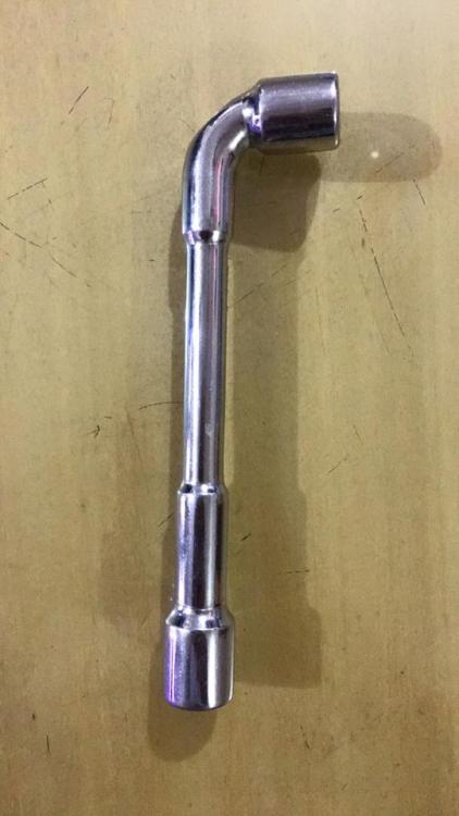
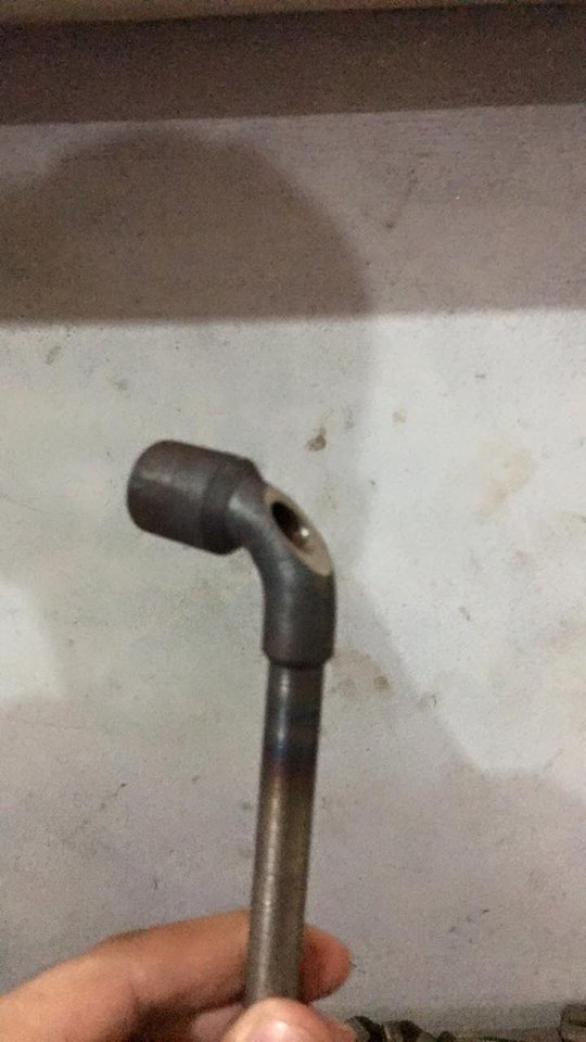
As u can see in the pics .. i have a straight piece. i have to make a bend ( imagine L shape )

-
- The bend is to be made from as near as possible from the socket. Longer heat spread will let the bend happen away from socket .
- 90 degrees is the required bend because after bend .. a drill hole is to be made at the bend .. different angle will cause drill to be out.
- i am heating it via induction.
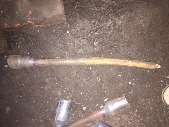
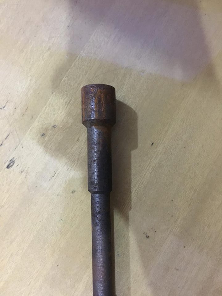
- The first pic is the piece without bend ( on which the bend is to made )
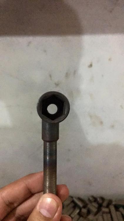
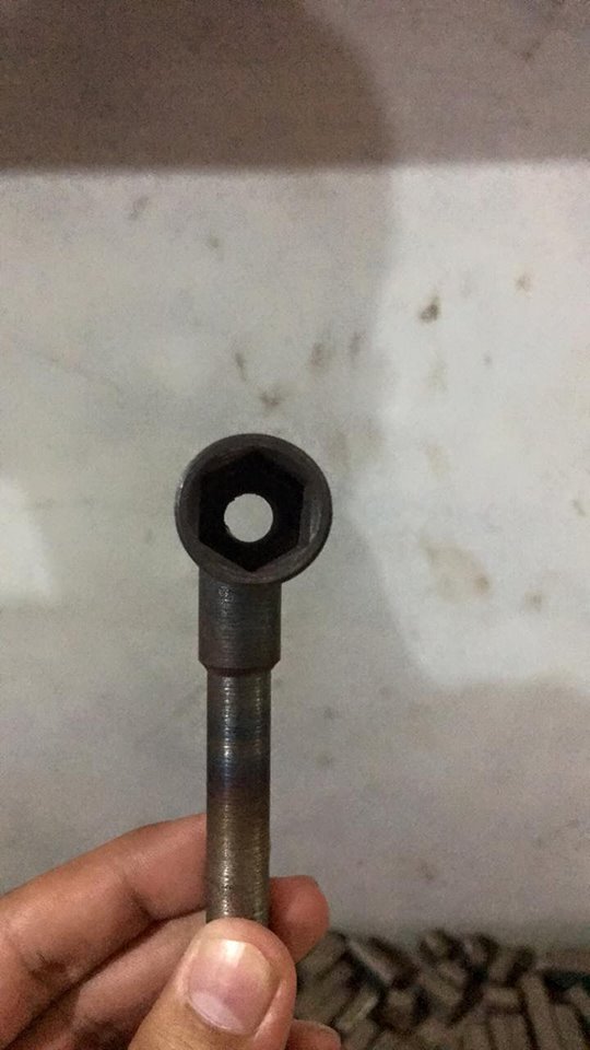
The second and third pics show the drill.
- In the fourth pic you can see the drill is wrongly made.( slightly on the left )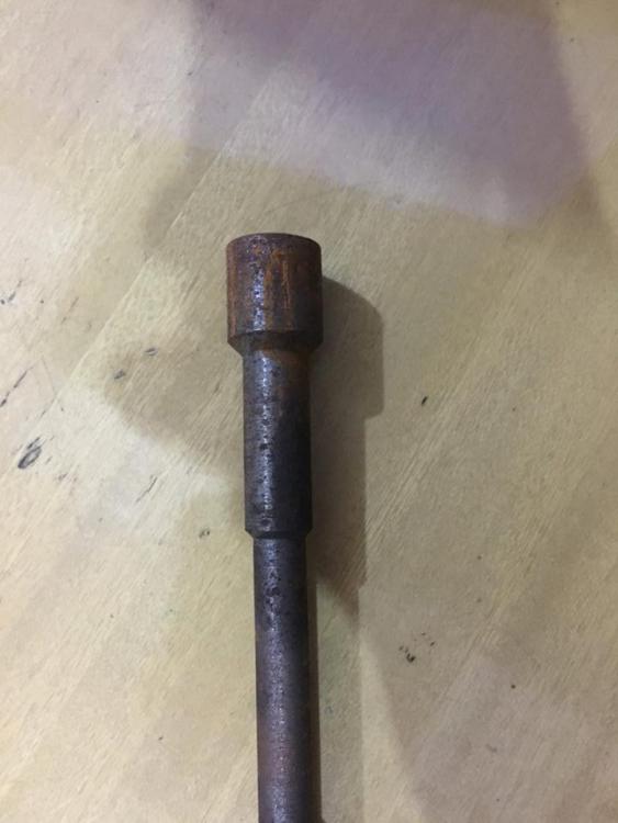

 4 hours ago, Alan Evans said:
A longer heat to spread the area of stretch?
A larger radius bend?
Heat on the inside of the bend to upset the metal there?
If you are welding the larger diameter section on, why not keep the bar straight and extend the larger section to it and make a tee weld?
How are you heating it, by induction or flame?
Alan
- The bend is to be made from as near as possible from the socket. Longer heat spread will let the bend happen away from socket .
- 90 degrees is the required bend because after bend .. a drill hole is to be made at the bend .. different angle will cause drill to be out.
- i am heating it via induction.
- The first pic is the piece without bend ( on which the bend is to made )
The second and third pics show the drill.
- In the fourth pic you can see the drill is wrongly made.( slightly on the left )
- I didnot understand " tee weld " part . please if u can explain. -
Hot forged steel (EN 8-D) .The problem occurs when the steel is to be bend at 90 degrees to give L shape. Does anyone knows a method or any machine ? (DIAMETER = 13,14,15 MM)
-
On 1/30/2016 at 5:02 AM, BIGGUNDOCTOR said:
What alloy of steel are they? How big, and what method is being used to make them?
we use EN8D and even chrome vanadium . The size ranges from 14" - 17" in length and 14 mm - 26 mm in diameter w.r.t. the length. And we use closed dies under drop forging hammers.(the mouth or the ends of the steel rods are pre-heated).We place the rods vertically under the hammer.
On 2/3/2016 at 7:50 PM, SmoothBore said:When working in the Auto Parts Business, that was an ever-present problem, with forging Automotive valves.
Rather than fight that losing battle, ... we just straightened them afterwards, ... by rolling them between flat plates, in a reciprocating "Thread Rolling" machine.
That process can be as simple, ... or complex, ... as you choose to make it.
If you GOOGLE "thread rolling" videos, you can get a perspective on how this might work.
Good Luck.
.
Thank you very much sir. But the bend occurs after the forging. So basically i have to straighten out a rod with variable diameters . I understood the process but can you point me out to something that can straighten a piece with different diameters?
THANK YOU .
-
the peices tend to bend when they are produced by drop forging under hammers after the ends are heated. any way the bending can be avoided ?
.thumb.JPG.5c7c40dcd705b32e1ed1bd4c506273da.JPG)


.JPG.9ca6e7130968957c35cafd8ddb211685.JPG)
can anyone explain induction heat treatment ?
in Induction Heating, Oil forges, etc
Posted
ok let me gather information about the setup then i will get back to you.
ok kind sir thank you.. will talk to them.