

rambo
-
Posts
44 -
Joined
-
Last visited
Content Type
Profiles
Forums
Articles
Gallery
Downloads
Events
Posts posted by rambo
-
-
hey guys,
im looking for someone or some company which can design my 10 Ton Closed Die Pneumatic Hammer foundation for me. we are shifting the setup to another location so the foundation is to be designed from scratch with vibration control in mind. Can you guys help me out with some recommendations of companies which do this?
Regards,
Rambo -
Firstly i apologise for taking so long in replying. i was out visiting customers in diff cities so i couldnt get back to u guys.
Rambo, does the stock that you are heating directly contact the floor of the furnace? Do you get scale or flux on it? At those temps iron itself is a pretty good flux and will help to break down the brick that the floor is made of. You may have to switch to a castable, possibly something magnesia based, think how they line crucibles and ladles and such in a steel works. The chemistry of the furnace atmosphere may be the part of the problem. The floor should be the coolest part of the furnace, so the temp rating may not be the problem. Is the damage to the door arch mechanical damage, say bumping stock into it? You might have to go with a harder brick in that location.
With all that said, there are some parts of the furnace that are probably going to have to be considered as "consumable", and will have to be replaced on a regular basis. I'm sure that the life can be extended between repairs, but nothing's perfect. If I were you, I would really analize what is causing the damage first, mechanical or chemical, and go from there.
yes ure rite.. it IS mechanical wear and tear. while loading of the stock in the furnace, the workers do bump the arc columns and the floor while placing the material inside. that isnt something that can be avoided a lot i guess cause of the sheer bulk of the raw material piece. still, i was thinking maybe i should go for some sort of ceramic fibre lining on the arc columns which would act as a cushion maybe?? but what kinda material mesh would be able to handle the temperature of the furnace to hold the fibre in place? a normal iron mesh would melt in seconds and let the fibre covering the columns fall in a heap.
I would switch to a different mfg or go with a high temp castable.
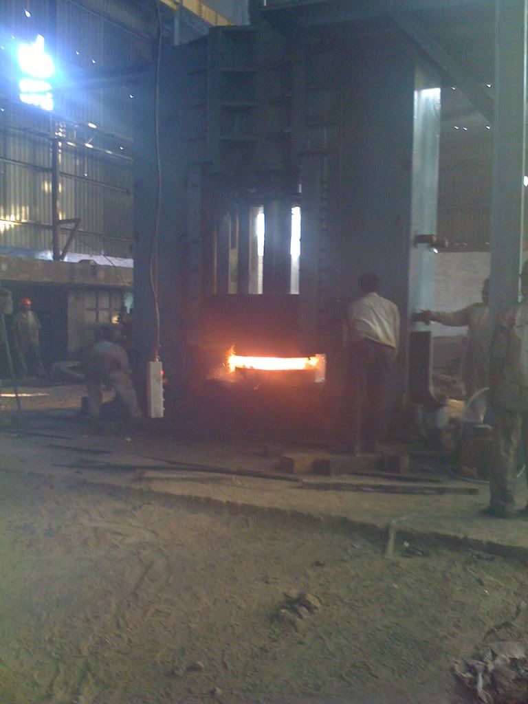
That's a BIG forge!
welder19
lol well that depends actually. i know of my competitors having even bigger ones.
Have taken some photos.
I am having problems getting these to load, so I will try to load some more later tonight.
Basically these show our door with the water filled/cooled rim around it.
The pipes coming down through the hood, with heavy air hose to make a flexible connection to allow the door to go up and down.
The cooling tank outside, this is above the level of the door.
We use Plicast 60LC (LEB70544) for our furnace floor a castable refractory, we purchase it from a company called Vesuvius Australia. the product sheet gives it as "a low cement, high alumina castable with excellent strengths and outstanding abrasion resistance.
If you are using bricks on the floor which way are you laying them, sides flats or on end. On end is the better way to lay them.
thanks for the upload forgemaster. hmm i also use a high alumina castable which is called IS-8 grade refractory brick. any idea how that compares with the one ure using?
my dad tells me that we've tried the water idea a few years back and it failed. could have been the design. the real prob is the sheet of cast iron which is covering the sides of the doors. at times the flame comes out through the sides and burns the place there, despite our putting heavier plates, its still something we need to repair regularly... maybe once in 2 months or so. in trying to think of a way that makes the door fit better in the furnace so that it fits tighter. its a door which is lifted open and close by a pulley system -
We use a water cooled door, have had it in use for about 4 years with not a problem. It is made from 75mm square hollow as heavy wall as I could buy. The SHS forms a watercooled rim around the outside, the middle is castable refractory. The water to cool the door is pumped in from a cooling tank placed outside. The connection is 1" gal pipe with heavy air hose to allow the door to lift up and down. Biggest problem we have is pumps stuffing up not the doors, we have replaced 2 pumps in 4 years, not bad seening as they run 24/7 I suppose.
If you want I could post some photos to assist with my description. The cooling tank is refilled by a ball cock.
Cheers
Phil
dear forgemaster,
yes, that would be a big help in understanding how it is that this system works. what temperatures does your furnace reach? i would think that at 1300'C temperatures, which is the limit i work at, the water would evaporate instantly. could you give me a drawing of the door structure, inside the furnace and outside as well so that i can understand the same?
i appreciate your effort.
What did your refractory supplier suggest when you told him you were having this sort of problem? (Or contact the original manufacturer of the stuff as they should know what works best for your situation and be *happy* to keep you as a customer!
well, the supplier had nothing to say.. both of them. they just stuck to their phrase that the quality of the bricks is not flawed. but even after explaining that im not playing the blame game, instead i want to know if there is something else they can recommend that i can use to increase my furnace life, they drew blanks. i even googled on the internet, but i cannot find anything which says, use such and such bricks made of this material. this will help increase ure furnace life as it can take so much more load, handles temp better etc etc.
so i thought i'd ask here at iforge. any help would be really appreciated. its a big drain on resources to have to build a 5 ton furnace every 2-3 months. -
Hi,
i just wanted some advice. I have 2 self designed and fabricated forging furnaces which go up to a max temp of about 1400'C. I use IS-8 Quality refractory bricks for lining the furnace walls and floor and have a mild steel door for the furnace. The door has ceramic fiber(coated with sodium silicate solution) lined in it to insulate and protect the 1 inch iron door. The Max capacity of the furnace is about 5 tons (depending on the size and shape of pieces being placed in it for heating).
My problem is that the bricks of the floor and arc(mouth of the furnace) as well as the door of the furnace does not last too long. every 2-3 months, 4 maybe if im lucky, the furnace needs to be repaired and the other furnace is taken into use. This is a major drain on my resources and repair time which could be used elsewhere is wasted here. Any suggestions on what i could use to help improve the life of the furnace. i will post the drawing of the furnace in a few minutes as soon as im done drawing it.
here we go, the drawing has been attached with the post.

thanks and regards.
rambo -
thanks guys. i appreciate it. :)
-
ummmm them i cannot contact... cause its er.... kinda a cracked version i am using :P
-
Hi everyone... it's been a really long time since i was last here. had been busy trying to come up with solutions for vibration control. in the end, i was only 20% successful. ah well.
anyways, i installed solidworks on my laptop for designing dies. the trouble is i don't know if it can reverse design. what i mean is, if i draw out the part which i want to manufacture on my closed die hammer on solidworks, will solid works design a closed die around the part and gimme the blueprints for the die? if this is possible, can someone please tell me how.
many thanks. -
Hi everyone,
i was wondering, how does one go about calculating the vibration forces generated by a hammer's impact theoritically?? i mean, i have all the information of the hammer, but if i want to know how much vibration is being generated in the ground after passing through the anvil, how do i do so?
Regards. -
Hi!, I do not see an easy way to lift the foundation to place springs etc under the foundation. The hammer is different from other die forging hammers, the anvil has been placed in a pit in the foundation, i.e. the hammer body is not fixed to the anvil but to the foundation. Instead of timber, neoprene rubber pads have been placed under the anvil as well as under the foundation. The spec of anvil and the falling weight are
1. Weight of anvil 200,000 lb.
2. Falling weight of ram + rod + upper die 18,000 lb.
I am enclosing a schematic of the drawing of the foundation and a 3D view of the hammer for better understanding.
Can you suggest if drilling holes in the ground till a depth of the foundation or more will be heplfull, probabaly some 75 ft away from the hammer. Or is there any other solution without having to move the anvil or foundation.
Picasa Web Albums - nitincharu - Untitled Album -
Hi! Fellow Forgers,
In our existing new forging hammer we are experiencing that there is great amount of vibration being transmitted to nearby areas. While building the foundation we used vibration isolation pads of Neoprene Rubber along with sand and boulders under the foundation, a 4 " air gap was also used on all four sides of the foundation to isolate the foundation from the ground. However, it seems that vibration is being transmitted from the bottom of the foundation only as the air gap would eliminate any vibration from the sides. Can somebody suggest any solution to this problem without disturbing the foundation. I was told by somebody that there are companies which drill holes in the ground at depths greater than the depth of the foundation. Help will be greatly appreciated as we have stopped the functioning of the hammer till this problem is solved.
Thanks,
Rambo -
Thanks, for the suggestion, have contacted solid works and qform.
Rambo -
Hi! All,
We successfully developed and commissioned a Self Fabricated power Hammer for forging gears wheel blanks up to 450 kg weight. Now we are looking for software for designing dies for material saving and die life, wherein we can feed the proof machined drawing of the gear and the program generates the die design/dimensions. Can any body suggest some such software.
Thanks,
Rambo -
ya, i guess i omitted to say that we do heat-treat the material after rough machining the forged pieces. since till now our clients have been doing the finishing, we didnt have to bother any further, but now that we want to do the finishing, i asked the question. But thanks for all the info. i am yet to carry out the tests for the lathe to see its current accuracy before i can take a decision on whether i can even do the finish machining on the current lathes or not. :)
-
hmmm well we are always up for experimentation... the hammer we put up kinda proves it. hehe. i know the dimensions are big, but its a standard sized shaft for heavy machinery. the raw material is carbon steel. they are machined after being forged to margins for machining.
-
Grinding on a lathe is not advisable, but if you have to do it, protect the slides as best you can.
What lengths and diameters will you be undertaking?
What metrology tools do you have to inspect / check the machines accuracy?
How accurately is the machine set up now?
As most lathe beds are worn near to the headstock end, I would suggest putting a long testpiece between chuck and tailstock, possibly using a travelling steady to support it, and take off a series of test finishing cuts, and use a micrometer to assess the accuracy of size along the length of the bar whilst in the machine, this could show up tapering or stepped worn areas,
You could then, if you have the facility, using a surface plate and a matched pair of V blocks and a dial test indicator, check for lobing, straightness and ovality.
I would also pose the question Why do you need to grind the surface, the size is only going to be as accurate as you can achieve turning, (Unless the grinding attachment has a finer feed thread arrangement than the lathes) and an excellent surface finish can be achieved using the proper tooling, feeds and speeds, along with polishing and burnishing tools.
well, i need to grind the surface for shafts with dimensions of 150mmX1500mm and upwards. that is the requirement of my client. moreover, the other lathes i have aren't good enough to handle such a delicate task. or i should say they are worse for the wear than this one.Spindle wear will dictate basic repeatability and deflection that you can achieve then add to that the variation in the carriage and bed. You could turn 10-30 parts and cut them off without making any offsets to the settings then check diameter of the pieces. That will provide a standard deviation, which is a good starting place to determine basic process capability. If the machine runs out .001 or more, you are wasting time installing a TP grinder.
sure. i will try this method out. actually, it had struck me to do this before but i wasnt sure if it would give me anything firm as a result. now that i have recommendation from u i will go ahead. I agree 100% with both previous posts, but want to add a couple additional details.
#1) Lathe accuracy can be dramatically influenced by how level and securely a lathe bed is in a shop. My 7' lathe will actually flex with the concrete floor as seasonal temperatures change. This allows the ways to twist slightly and only cure is to re level the lathe again (on all axis) to correct precision cutting accuracy.
#2) One of my first factory machining jobs was to precision grind/profile diamond grinding wheels used in the optical lens field. All grinding was performed on a lathe with a tool post grinder and all radii generated through grinding in the freehand mode. Lathe ways were covered with heavy fabric such as shop apron materials and a strong industrial shop vac system was used to collect as much dust as possible. Before covering the ways, all oil was wiped off/dry. After each grinding operation was completed oil was applied in order to float any remaining dust up and all was wiped off again. Ways were re oiled again for regular typical type machining operations, or wiped dry again to begin grinding another piece.
Hope this helps!
BE safe
yep. it helps. the only trouble is, in india there is a lot of dust in the air so keeping the bed clean is only a dream. which is y there are some fine lines on the slides. still, im going to try the suggestions above to check how accurate the lathe is for a simple job and then decide on the option of going for a grinder tool post.5 micron?
What are you doing that could require that kind of acuracy?
For anyone who doesn't know what a micron is, 1mm is 1000 microns, human hair varies from 60 to 100 micron, on average 40-50 micron is the limit that the human eye can see.
welder19
well, mostly for grind finishing for a large shaft.Microns are usually surface finish units, 5 micron would be a highly polished surface, and if this was to be a regular item, I would invest in the proper machine for the job.
In the past I have produced highly polished bores for hydraulic pistons to be fitted to on lathes, but not by grinding them. External finishes are a different thing altogether.
yep. it is external finishing for the job which has to be a grind finish to a tolerance of 5 microns and maybe lesser in some cases. -
Hi! John, I am waiting for quote from you.
-
Hi everyone.... i have a Tovaglieri lathe which is a 2nd hand one. been using it for about 3-4 years now and i wanted to know how i could test it to see its precision and accuracy. i wanted to attach a tool post grinder with a DRO for very high precision grinding tolerances.(upto 5 Micron) and was wondering if it was worthy of it or not. any ideas what all i could check and how i could check the same?
-
Thanks John for your input. I would certainly like to re design the valve and chest. However, I need to start production and can simultaneously start making a new valve with your help. In the meanwhile I had an idea to improve the existing design, basically I am looking at reducing the 4 " length of the spindle in the middle to 3.5 ", the 2" size of the spools would remain the same. This way the valve exhaust would always be open by about 1/2" to allow quick release of the steam, thereby reducing the pressure build up on the valve. Do you think this might help? Please also send me a quote for the design suggested by you.
Rambo -
this is the pic of the hammer....
-
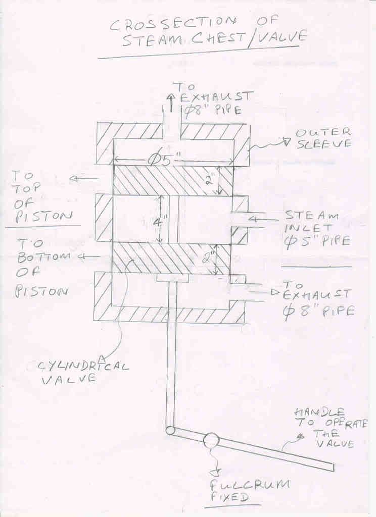
Hi! All, Thanks for the interest, I finally have a sketch of the valve attached, I agree that without the existing design any suggestion would be difficult. The position of the valve is in neutral in the drawing, when the handle goes up the valve goes down and there is load on the handle which tends to take the handle up, which the operator struggles to control. I can see what John is saying, it is back pressure from the exhaust. Would like to see some standard designs of the valve which can eliminate/reduce the back pressure. We have not really copied any design but only tried to improvise our free forging hammer design to a die forging one based on experience and info available on the net. -
in my experience(which is jus about 8 months, hehe ) a cold anvil will break when hit with a sufficiently large force. thus heating is a very very good idea.
i use the same method as said above in many places of using a heated piece on the anvil and letting it absorb the heat. -
lol. im not about to post a vid.
 hehe. still, it is gonna take a bit of time cause im kinda stuck in 2 projects simultaniously. will up as soon as i can.
 -
sure. i will post some pics in a day. thanks for the responses guys.
-
Hi! All,
I am having problems with my self fabricated 6.5 Tons Power Hammer running on steam. When the operator lifts the handle to take the ram up he is unable to control the handle as there is an external force on it to move up. There is tremendous load on his hand to keep the handle from going up and thereby the piston hitting the top of cylinder. I believe this has something to do with the design of the motion valve, can some body help me with this?
Thanks
Rambo


Hammer Foundation designers
in Blacksmithing, General Discussion
Posted
Hi. thanks for the reply. I will get in touch with them. Only thing is, i think they just manufacture hammers or supply spares. i dont think they are into foundation design. still, anything is worth a shot. thankyou.