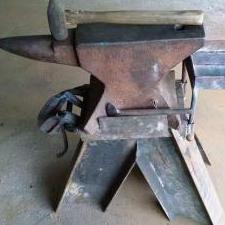
JHCC Posted June 8, 2019 Share Posted June 8, 2019 I just acquired a used inverted hydraulic press for $47 from the industrial surplus warehouse, and I want to convert it to a light-duty forging press. I will be documenting the design and build process in this post and its comment thread. Anyone is welcome to comment and make suggestions, especially since my experience with press construction is essentially zero! So for starters, this is what I’ve got. Here it is in the warehouse: Fortunately, it fit in the back of my Honda: Step one was to take off the rubber shield that used to wrap around the back: And cut off its supports: View from the front (operator's side): View on the left side: View of the back: View of the right side: Close-up of the hydraulic pump and reservoir: Close-up of the attachment of the frame to the underside of the top: Close-up of the top of the ram, as bolted to the existing tooling: Close-up of the control lever (in for up, out for down): Close-up of the motor plate: Quote Link to comment Share on other sites More sharing options...
JHCC Posted June 8, 2019 Author Share Posted June 8, 2019 How the bottom of the cylinder is mounted to the frame: On/off switch for the motor: The motor is wired for a 115 volt plug and seems to run just fine. The ram is 1-1/2" in diameter and has a 7-3/4" stroke. I don't know what the diameter of the piston is (I haven't found any markings on its housing), but the outside of the cylinder is 4-1/2". The ram as it stands moves very slowly: it takes a bit more than 30 seconds for it to move up its entire stroke (I haven’t timed the down stroke yet). I don't know what might be done about this, but as Frosty said to me once, even a slow press will do an amazing amount of work. I now have to think about how to adapt this to forging. I had an idea in my head for attaching a moving die holder that would pull the top die down onto the workpiece, but that was before I knew that the top is 1-1/4 solid steel that would present some challenges for making holes for the frame's uprights to move up and down in. More to come! Quote Link to comment Share on other sites More sharing options...
JHCC Posted June 8, 2019 Author Share Posted June 8, 2019 Overall dimensions are 24” wide x 24” deep x 35-1/2” tall. The top is 1-1/4” solid steel plate. Total weight is about 500 lbs. Quote Link to comment Share on other sites More sharing options...
Frosty Posted June 8, 2019 Share Posted June 8, 2019 By 1-1/4" ram, that's the diameter of the rod coming out of the piston. Yes? It's displacement will make it pull faster but will reduce working force. It'll push harder but more slowly. Is 30 seconds, to extend or retract? That's a small pump but physical size doesn't indicate a lot about it's output. The hydraulic pumps on our drill rigs were smaller than a 3 lb. coffee can but made a lot of GPM and PSI. The larger rig was driven by a 453 Detroit Diesel (unaffectionately known as a SCREAMIN Jimmy.) The 1.5 HP Baldor motor is a workhorse and makes it a good buy all by itself, single phase is the deal maker in my book. 1-1/4" solid steel table would cost more than you have into it all by itself. It's a SWEET score Jhon! There are tricks for speeding up the GPM without effecting the psi. Is the control valve detent Stop or detent centering (automatic return)? If the ram just stops when you release the lever you can preposition the dies close to the thickness of the work so travel speed isn't as important. Yes? Also, smaller dies mean greater psi applied to the work and psi is what moves the steel. Yes? It's making me itch to plug it in, listen, measure and time things before I start cutting and welding. I can't tell you how happy I am I don't live close enough to browse the HGR warehouse. This is going to be a fun project and a workhorse tool when you get done with it. Frosty The Lucky. Quote Link to comment Share on other sites More sharing options...
JHCC Posted June 8, 2019 Author Share Posted June 8, 2019 11 hours ago, Frosty said: By 1-1/4" ram, that's the diameter of the rod coming out of the piston. Yes? Yes, but 1-1/2”, not 1-1/4”. 11 hours ago, Frosty said: Is the control valve detent Stop or detent centering (automatic return)? If the ram just stops when you release the lever you can preposition the dies close to the thickness of the work so travel speed isn't as important. Yes? The ram just stops when you release the lever, so I guess that’s detent stop? It doesn’t appear to do anything automatically. Quote Link to comment Share on other sites More sharing options...
Frosty Posted June 8, 2019 Share Posted June 8, 2019 That's another 3/4 sq/in subtracted from the ram area. At 500 psi that'd reduce the working force by 375 lbs. I just grabbed those numbers out of the air for the purposes of discussion. I don't know enough to be specific. Subtract the area represented by a 1-1/2" dia. rod from a piston area to get an idea of the difference in working force between push and pull. You don't need to know what the piston area is to judge the difference in working force. Yes? Okay, I pulled out my calculator, my calc. watch has tiny buttons. a 1.5" dia. rod represents 1.77sq/in (yes I rounded) and at 500 psi, it represents about 883.5 lbs of working force between pull and push. Regardless of the actual piston size. I'm just looking at the rod's effect on working force. I highly recommend you change hydraulic fluid on GP. (General Principals) Now if you were to disconnect an output hose and let it pump till it gurgles. Don't run the pump dry, it's not good for them but won't damage it if you don't let it run dry long. Anyway, let it pump itself out into a measured container and time it. You'll have a good estimate of the pump's unhindred GPM. For example 10 seconds to fill a gallon container represents approx 6 GPM. unhindered. Unhindered means it's not pushing against anything but the hyd fluid and friction. If you have to test, that'll give you some numbers to work with. Hopefully the pump has a data plate and we can skip all the testing. Change the fluid anyway. ATF is a good choice if there isn't a spec on the data plate. Thin fluid flows faster and is still uncompressible. Frosty The Lucky. Quote Link to comment Share on other sites More sharing options...
JHCC Posted June 8, 2019 Author Share Posted June 8, 2019 I found a plate on the underside of the pump: it's a Northern Tool model 10562. According to their website, it runs .75 GPM at 1800 RPM. The motor is rated at 1725 RPM, so I suppose it's marginally less than that. It's rated with a maximum PSI of 3,000 (continuous) and 4,000 (intermittent). 1 hour ago, Frosty said: It's making me itch to plug it in, listen, measure and time things before I start cutting and welding. Here's a quick video of the full cycle: About 34 seconds to fully extend and 30 seconds to fully retract. Quote Link to comment Share on other sites More sharing options...
Frosty Posted June 8, 2019 Share Posted June 8, 2019 Ah, NUMBERS!! Yes, you have a noncentering detent valve. The ram just says were it is when you release the valve. It's a GOODNESS thing. 0.75 GPM will be the rating . . . without a load or Unladen, terms are coming back and I haven't dug out my hydraulics books! I love thinking about these things, brings back memories. 1735 RPM motor is close enough not worry about. 4 second difference unladen on a 7 3/4" stroke. it will be greater laden of course, everything moves more slowly under load. I'm going to grab a number out of the blue sky to work with for now. I'll let YOU determine how many sq" the piston surface has, you have the GPM rating and how fast it moves 7 3/4". You can do volume calcs yes? If not let me know. Just for conversation's sake I'm grabbing 4" dia. piston guesstimating from the 4.5" OD on the cylinder as measured. Call it about 12.5 sq. in or piston surface x 3,000psi says it'll have 18.8 tons of working force PUSHING. OR using it's intermittant 4,000 psi rating up to 25. tons working push. You can get more accurate work force numbers by pulling an end off the cylinder and measuring the piston. It'll be a good time to check and maybe replace the seals and Orings. It's a good GP thing and easy to do. Pulling will be faster but weaker. This is going to make a fine forge press. Good score John. Sounds normal, the rhythmic sound is normal for a roots type pump. I don't hear anything alarming. Frosty The Lucky. Quote Link to comment Share on other sites More sharing options...
JHCC Posted June 8, 2019 Author Share Posted June 8, 2019 So if I understand correctly, changing the GPM will change the speed but not the pressure — is that right? Quote Link to comment Share on other sites More sharing options...
Frosty Posted June 8, 2019 Share Posted June 8, 2019 Yes, RPM=GPM. Torque = psi. on any give pump. The only practical way to improve speed with that set up would to reduce friction in the lines and fittings it's squealing in the video so I don't think there's much to improve. Frosty The Lucky. Quote Link to comment Share on other sites More sharing options...
JHCC Posted June 9, 2019 Author Share Posted June 9, 2019 Okay, design time. As I see it, I have three main options (four, really, but more on that later): I. Fixed frame and cylinder above the table: II. Moving frame, floating cylinder below the table: III. Moving frame, fixed cylinder fastened to the underside of the table: The fourth option would be to flip the whole thing upside down, and making something like Version I. However, this would expose the mechanism (hoses especially) to hot steel, would require building a base strong enough to hold 500 lbs, and — critically — assumes that the existing welds connecting the cylinder supports to the underside of the top would be strong enough under tension. Thoughts? Quote Link to comment Share on other sites More sharing options...
Peppie Posted June 9, 2019 Share Posted June 9, 2019 Your on the right track. You need to s rap the frame it is in, less that 1 1/4" plate. I vote for an "H" frame style. Keep it simple. Less moving parts, the better. Nice score. You couldn't buy the fluid for your future press for the price you payed. Quote Link to comment Share on other sites More sharing options...
pnut Posted June 9, 2019 Share Posted June 9, 2019 6 hours ago, JHCC said: The fourth option would be to flip the whole thing upside down, That was the first idea that popped into my head. Then I had the same concern about weight and the integrity of the welds. It may be easiest to build an H frame as Peppie said, but I'd not abandon the idea of flipping it over yet. Pnut Quote Link to comment Share on other sites More sharing options...
Frosty Posted June 9, 2019 Share Posted June 9, 2019 21 hours ago, Frosty said: reduce friction in the lines and fittings it's squealing in the video ARGH! I hate quoting myself but a mistake is a mistake even a typo. Your hydraulics are NOT squealing so the lines, valves, etc. are NOT inducing undue friction so it's okay. The less frame you have moving the more sturdy it will be and you want as rigid a press as is practical. I don't see a sketch I really like so much. I'd mount the cylinder to the bottom of the table as directly as possible and weld a frame to the top to support the anvil die above. This way the ONLY moving component is the press die and guide. The press die guides slide around or in a track in the anvil die frame's vertical members. The mechanism is the same as manual hydraulic presses you see for installing bearings or straightening light shafts. It's just compact and robust, It'll develop a good 25 tons of force pushing. I recommend welding the frame but you COULD bolt and pin it all together like a manual press. The existing table has a hole large enough to pass the cylinder shaft now, not the pulling extension. Yes? You can lose the cylinder mounting frame if you want to get a little crazy. I'd be sorely tempted to drill and tap the bottom of the table to accept the cylinder bolts. Lose the nuts and leaving the lock washers bolt the cylinder directly to the bottom of the table. Don't drill and tap all the way through the table top or you'll have scale in the holes. Yes? The existing cylinder mount is for pulling against making it rigid enough for a pusher will require some fab work or the ram will want to lean towards the most give. Bolting the cylinder directly to the table is the simplest way I can think of to turn it into a robust and solid pusher. That's just a thought, probably how I'd do it. I've worked with this stuff too many years to be intimidated because it's "HYDRAULICS! ". Direct mounting will keep the vulnerables under the table where they're safe. It'll allow you to shorten the hoses or even replace them with steel pipe, my favorite for reducing the entropic waste of flexing and stretching hoses. The press die (Moving die) would move upwards but . . . The die carrier guides fit between the post members and has flanges to prevent it from cocking sideways. It all just slides in the space the verticals. Yes? A few thousandths clearance is plenty say a business card's worth when you weld things up. Oil isn't a good idea, crud sticks to it and might cause issues. I like channel iron for the anvil frame. Each vertical being 2 pieces of >6" x 8lb. channel flange out with spacers between a few thousandths wider than the press die carrier on each side. It'll look like I beam, do not use I beam, the fab is too complicated. The bridge across the top that holds the anvil die can be one WIDE plate the same thickness as the spacers. Even if it's only 1/2 thick if it's say 10" wide a mere 25 tons isn't going to flex it let alone deform it. If you make the top die holder the ID of the frame and sandwiches the bridge member it can't go anywhere. It has the bridge it's have to deform in whole while trying to spread the posts which are anchored together by the bridge member. Rock flippin solid. Yes? The ONLY place to be careful to get right is welding the verticals to the table and there're a LOT of inches to get good welds. If you want to look at structural shapes, sizes, weights, etc. Coyote Steel & Co. had a good PDF listing more than a boy could use in this lifetime. C channels are a couple pages down in the steel shape section. I'd link it but it's a commercial site, the name alone should do it. Well, I think that's enough to confuse everybody for now. Those are good concept sketches John, just not how I'd build a press with that machine. Frosty The Lucky. Quote Link to comment Share on other sites More sharing options...
JHCC Posted June 9, 2019 Author Share Posted June 9, 2019 On 6/9/2019 at 1:54 PM, Frosty said: I'd mount the cylinder to the bottom of the table as directly as possible and weld a frame to the top to support the anvil die above. Like this? That’s a very interesting idea, and one I like a lot. I will have to give this some thought. On 6/9/2019 at 1:54 PM, Frosty said: The existing table has a hole large enough to pass the cylinder shaft now, not the pulling extension. Yes? No. The cylinder shaft is 1-1/2”, and the hole for the pulling extension is just over 1”. I could enlarge it with a die grinder, though. On 6/9/2019 at 1:54 PM, Frosty said: I like channel iron for the anvil frame. Each vertical being 2 pieces of >6" x 8lb. channel flange out with spacers between a few thousandths wider than the press die carrier on each side. It'll look like I beam Like this (seen from above)? Quote Link to comment Share on other sites More sharing options...
Frosty Posted June 9, 2019 Share Posted June 9, 2019 Yep, you have the picture of how I'd approach the project. I'm lazy and am cautious with high energy machinery so I like the strongest, minimum modifications. I REALLY wish I had good basic 2D cad or a working scanner so I could post a couple sketches. Another thought just occurred to me. If you shorten the ram mounts and bring the hyd. pump, reservoir, etc. closer to the table top, you can shorten the legs and make it a comfortable working height between the dies. Hmmmm? Right now I'm juggling the components in my mind but those aren't likely to make working differences. I just can't help it, it comes from working with hydraulics on drill rigs so many years. If you've ever seen hyd. hoses jump when someone throws a valve you've seen wasted energy. The hoses jump because the hyd fluid is stretching woven steel reinforced hose and just sucking the energy. I used to replace every hose I could with steel line, made things run stronger, faster and cooler. It isn't something to worry about on your forge press, I just can't help myself. Frosty The Lucky. Quote Link to comment Share on other sites More sharing options...
JHCC Posted June 9, 2019 Author Share Posted June 9, 2019 Here’s a basic question, Frosty. Let’s say I take the big nut that’s currently welded to the bottom of the pulling extension and weld that to the underside of the moving die holder. Can I rotate the shaft within the cylinder to screw the shaft in and out? Or would I have to rotate the entire unit? Quote Link to comment Share on other sites More sharing options...
JHCC Posted June 9, 2019 Author Share Posted June 9, 2019 Also, what do you think of Rick Rabjohn’s idea of the moving guides as sections of square tube sliding on the outside of the posts? (Sorry for the fuzzy image; it’s from a screenshot of this video.) Quote Link to comment Share on other sites More sharing options...
Frosty Posted June 9, 2019 Share Posted June 9, 2019 23 minutes ago, JHCC said: Can I rotate the shaft within the cylinder to screw the shaft in and out? Yes, it shouldn't be a problem, piston and cylinder are round. Preventing it from turning in use is one reason for guides. 5 minutes ago, JHCC said: moving guides as sections of square tube sliding on the outside of the posts? I'm not a fan. It's trickier fabrication and isn't nearly as robust. Tubing is a lot more likely to warp and pull when you weld it and this plan involves welding a LOT of sq. tubing. The guides don't clear crud as easily either. If the posts were square steel bar or crazy heavy tubing schd. 100? it'd be rigid and strong to a fair the well. There are some easy tricks for welding C channel to prevent pulling that don't apply to tubing. If you wish to go that way I'll be honored to help regardless. Frosty The Lucky. Quote Link to comment Share on other sites More sharing options...
JHCC Posted June 9, 2019 Author Share Posted June 9, 2019 I’m just weighing my options at this point, part of which is thinking about what stock they had in the drop bin at the steel supplier the last time I was there. I have some C-channel already, but I think it’s probably too light (about 1-1/2 x4), plus it’s holding up one of my grinders. Quote Link to comment Share on other sites More sharing options...
Frosty Posted June 9, 2019 Share Posted June 9, 2019 Of course, it's brainstorming time. I'd be surprised if you made hard plans at this stage. You could probably get away with that C channel what 4" 5lb? but you'll be happier with a more rigid frame. Bet that's a rock steady grinder stand. Imagine one with 4 members laughing at 25 tons. My suggestions are just that, keep your eye on the drops, I'll bet a box of doughnuts and the boys in the yard would set the good stuff aside for you. Hmmmm? Don't get in a hurry but brainstorm with vigor. Frosty The Lucky. Quote Link to comment Share on other sites More sharing options...
JHCC Posted June 9, 2019 Author Share Posted June 9, 2019 This is one of a pair; the other one is the vertical part of my treadle hammer. Quote Link to comment Share on other sites More sharing options...
bubba682 Posted June 9, 2019 Share Posted June 9, 2019 If it were me i would weld an h frame to the table i'd use 2x4 tube steel at a 1/4 '' thick minimum, the table in the pic looks 1'' thick so i would sweat the weld zone on the table to 250 deg stick weld 3 passes all the way around the tubes .I'd put wheels on the legs i love being able to move mine around the shop and you will want to increase the speed of the ram speed is your friend on a press.I think i read your at 18 ton thats no joke your welds will be tested make sure theres no undercut or porosity and thats more than enough squeeze everybody now wants 50 next it'll be a 100.Mines at 24 ton its been squeezing steady for a year Quote Link to comment Share on other sites More sharing options...
JHCC Posted June 9, 2019 Author Share Posted June 9, 2019 1 hour ago, Frosty said: If you shorten the ram mounts and bring the hyd. pump, reservoir, etc. closer to the table top, you can shorten the legs and make it a comfortable working height between the dies. As it stands and adding an eyeballed 8” for the rod and die, the working height would be roughly between my navel and the bottom of my ribcage. If that’s too high, I can lose about 9” off the legs without having to move anything else. 43 minutes ago, Frosty said: keep your eye on the drops, I'll bet a box of doughnuts and the boys in the yard would set the good stuff aside for you. Hmmmm? My guys have their operation down: there’s a section of the warehouse reserved for drops where you can browse as much as you like. Once you’ve picked out what you want, you weigh it, tell them the amount, and they give you a price. Quote Link to comment Share on other sites More sharing options...
Frosty Posted June 9, 2019 Share Posted June 9, 2019 That sounds like a decent working height, I could live with it. If what you have is 4" C channel we can make it plenty strong and rigid, it'll just take a couple gussets to make it rock solid. No big deal. Frosty The Lucky. Quote Link to comment Share on other sites More sharing options...
Recommended Posts
Join the conversation
You can post now and register later. If you have an account, sign in now to post with your account.