John Larson Posted July 15, 2012 Share Posted July 15, 2012 You guys have so much energy. I'm thoroughly impressed with your workshop DD. Rick thanks for the e-book in entirety and thanks DD for the relevant chapter. I've leaqrned a great deal today. Quote Link to comment Share on other sites More sharing options...
Dillon Sculpture Posted July 15, 2012 Author Share Posted July 15, 2012 The closest 6B to you RIc is at Machinco, go fer it! You need a few for machines :blink: A bit of encouragement to you as well Woody! You won't be diappointed. Found some fiber asphalt foundation sealer today that should work nicely for the wood, it weighs in at 1800 pounds. Quote Link to comment Share on other sites More sharing options...
Ric Furrer Posted July 15, 2012 Share Posted July 15, 2012 It is not so much locating a machine, but its foundation. The plans I have call for an eight foot deep hole a bit larger than the machine. I would like to speak with someone who has one running to see what they think. My 3B has a four foot deep concrete pad and then wood under the hammer..pictures somewhere. It seems OK, but I am not running her 24/7 though I have done some three day runs where she was full tilt for a few hours on end....rather impressive when the steel is hot and the tooling allows me to simply press the treadle and hold on for 42 blows at max. Side note: That same job took 47-50 blows when the forge was heating up and 36 blows just before lunch...so a little temp can make a large difference. If you feel ten-15 blows is not a large difference on a 3B then, well...you must work under some big tools. Danger...I need more tools like I need a larger belly, but a bit larger shop, well...THAT would be good. Ric Quote Link to comment Share on other sites More sharing options...
Dillon Sculpture Posted July 16, 2012 Author Share Posted July 16, 2012 Well Ric, I guess that is a advantage of the steam hammer. My hammer only weighs 15000 or so total and it disassembles into sections that can be easily transported and lifted with a 5000 lb. forklift. Moving and setting the 6B with a total weight of 38000 lbs. is a whole other story and in comparison, I would think rigging, transportation and installation would cost more than the foundation itself. I have $300 in equipment rental, $200 in rebar and $1200 in crete for both hammers, the wood was milled here from clearing the land for my shop. Of course my time will add up sooner than later but if they aint working their not working... Quote Link to comment Share on other sites More sharing options...
Dillon Sculpture Posted July 16, 2012 Author Share Posted July 16, 2012 Wood is sealed, rebar done, set in the wood and anvil tomorrow and form it up. The 200 has landed, bolt it down and add air. The ram to anvil ratio had been bugging me so I pull the ram out of hiding and gave it a way in, 500 lbs. with the top die. The piston is also part of the weight rating on the hammers which we calculate at 200 lbs. Seems like an odd weight and it really doesn't help the anvil ratio quandary. I guess since there is no surviving information on Niles Bement Pond steam hammers it will be a mystery. Quote Link to comment Share on other sites More sharing options...
r smith Posted July 17, 2012 Share Posted July 17, 2012 You will set the anvil on the wood so the wood does not float up in the wet crete? I still might bolt the thing down. Looks good. smith Quote Link to comment Share on other sites More sharing options...
Dillon Sculpture Posted July 17, 2012 Author Share Posted July 17, 2012 Yep, Quote Link to comment Share on other sites More sharing options...
Ric Furrer Posted July 17, 2012 Share Posted July 17, 2012 The wooden box form I made when I poured the 3B foundation lifted and popped some of the tapcons and angle iron I had holding it down...ended up placing quite a bit of ballast to keep it down.....made a stack of steel and stone some five feet high in a hurry....apparently concrete is heavy. Looks very good Michael.....in a few weeks after the cure you can fire it up. Ric Quote Link to comment Share on other sites More sharing options...
basher Posted July 17, 2012 Share Posted July 17, 2012 I did similar with my 200. screwed the box down and added steel as the concrete was pored , I checked the beams holding the box with level to keep it ...level. Quote Link to comment Share on other sites More sharing options...
monstermetal Posted July 18, 2012 Share Posted July 18, 2012 Looks like your having a good bit of fun ol buddy..... Cant wait to see some video Quote Link to comment Share on other sites More sharing options...
Dillon Sculpture Posted July 18, 2012 Author Share Posted July 18, 2012 All dress up and no where to go... Got it wrapped, set and formed. Looks a bit anal but I'm having to dump the concrete a yard at a time with a rubber tire loader (it's good to have a friend in the grading business) The driveway up to my shop is 300' at 20% grade, just don't want to chance a 30 ton truck popping the crete all the way up. Quote Link to comment Share on other sites More sharing options...
Sask Mark Posted July 18, 2012 Share Posted July 18, 2012 If you have access to one, a concrete line pump can probably pump that concrete from the bottom of the hill. The drawback (besides cost) is you waste some concrete in the lines. Pumping also affects the air entrainment of the concrete so it should be noted with your concrete supplier that it will be pumped so they can compensate at the mixing stage. Quote Link to comment Share on other sites More sharing options...
Dillon Sculpture Posted July 18, 2012 Author Share Posted July 18, 2012 Cant wait to see some video Video? I was hoping to get some seasoned power hammer men down here for a weekend or so... I would love to get all four machines running some serious stock at the same time, of course that means a bigger forge! Anybody have thoughts on using pvc to pipe the exhaust outside? Quote Link to comment Share on other sites More sharing options...
Dillon Sculpture Posted July 19, 2012 Author Share Posted July 19, 2012 Started pluming the beasts today. Here is a sketch of my linkage ideas. The eccentric would raise the head to attention and the chain would allow some downward movement of the ram position, from a lower cycle to the extreme, it would single blow. Quote Link to comment Share on other sites More sharing options...
nonjic Posted July 19, 2012 Share Posted July 19, 2012 Loving this thread! cant wait to see the videos. Seems weird putting so much timber under an anvil (not saying its not a good way to do it, just that I have never seen it done like that!) Can you draw a layout of the valves, tubes and motion gear? I might be able to chip in with some ideas when I see what is really going on with it. What I usually do on 'unknown' hammers is 'project' the valve tubes, and valves (ie roll up a piece of paper into the tube, and press it against the ports. Wrap a piece of paper around the valve so it marks the bands / drilling / cutouts etc. You know the valve travel in the tube so you can then overlay the 2 tracings and move them relative to each other to see where the air is going, and why. The trick to steam / air hammer valving is to fully understand that the hollow center of the valve is the exhaust for top & bottom cylinder air, there is usually a 'live' band of air around the middle of the spool that charges top or bottom of the piston head whilst the 'hollow' valve exhausts the opposite. Ive made cardboard models before of self recipricating air hammers that have a throttle valve that actuates the control valve via a 'sword arm' or lever. It helps the understanding :) Quote Link to comment Share on other sites More sharing options...
Ric Furrer Posted July 19, 2012 Share Posted July 19, 2012 Good idea John...I'm stealing that one. So what Massey do you have for sale and what are the prices? Ric Quote Link to comment Share on other sites More sharing options...
Dillon Sculpture Posted July 19, 2012 Author Share Posted July 19, 2012 Hey John, your advice is most welcome. The best drawing I have found is on Anvil Fire, power hammer page #2, Niles Bement. Your archives are probably a wonderment to all interested in hammers, isn't Massey responsible for the first steam hammer? My skills rendering the inner workings of the hammer are not going to be sufficient but, my first hand experience may have some bearing. As the motion valve lever is lowered the ram cycles lower and lower until becoming basically a clamp, as you raise the lever the stroke becomes higher until the piston smacks the head. The throttle only increases the severity of the motion. As I have studied Grants set-up the advantages I see are, #1 the ram is in the up position when approaching the hammer with the work. #2 a hand activated lever allows him to lower the ram through the motion valve which is also connected to the foot treadle via a chain. In my drawing I am trying to use the existing levers (so the operation of a driver is still possible) and KISS... My worry with the sketch is overcoming the force of two springs instead of one, I really want the action to be light and responsive. Quote Link to comment Share on other sites More sharing options...
JNewman Posted July 20, 2012 Share Posted July 20, 2012 Good to see the foundation going in. The steam hammers at stelco as well as the Massey were set up on timbers like you are doing. I believe the steam hammers had pilings under them as well but the soil under them was probably all fill. That paper idea is a really good idea John. I had actually thought about measuring and mocking up the valves in my Massey using plywood or hardboard, but paper or cardboard makes way more sense. Quote Link to comment Share on other sites More sharing options...
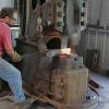
Dillon Sculpture Posted July 20, 2012 Author Share Posted July 20, 2012 Got the 200 running today! Ran ok on my small compressor but it won't keep up at full tilt. I did a mock up of my linkage with some mixed results, maybe a bit more trial and error to get it right. When the ram is given enough air to raise, it becomes paralyze mid-stroke, you have to tickle the motion valve to get it to cycle again. I remember Mr. Larson spoke of overcoming equal pressure on the valve? I did find It has a easier time of overcoming this pressure equality the higher in the stroke the ram is, more study is at hand. I may just have to forge a bit tomorrow and think about it :huh: Quote Link to comment Share on other sites More sharing options...
John Larson Posted July 21, 2012 Share Posted July 21, 2012 Danger Dillon, the 3-position valve is what is causing the hammer to "steam lock" at the middle position. Once reciprocating inertia will tend to allow that middle position to be crossed without the tup stopping. Once stopped, the throttle lever won't get it to move (except possibly by some differential leakage). Maybe John N knows a standard way of handling this. I suspect there may be several approaches. I think you have to set priorities on the two controls, probably making the throttle valve secondary so that it has its effect after the position control has been "jiggled" a bit to get it off center. That is what the hammer man always seems to do in old film clips I've seen. Quote Link to comment Share on other sites More sharing options...
Dillon Sculpture Posted July 21, 2012 Author Share Posted July 21, 2012 Thanks John, several approaches is what I'm looking for. Another idea I had was combining the two controls into one foot control. Heel-toe for the throttle and up-down for the motion valve? I found another picture of the inner workings. Quote Link to comment Share on other sites More sharing options...
iron woodrow Posted July 21, 2012 Share Posted July 21, 2012 this is one of the ones i have been looking at to get my head around what i need to do..... http://www.flickr.com/photos/41924895@N07/6763182577/in/photostream/ i dont know if i like the sound of heel-toe, because i like to put my weight onto my heel,, it would take it out of you to be virtually standing on one leg all day! Quote Link to comment Share on other sites More sharing options...
Dillon Sculpture Posted July 21, 2012 Author Share Posted July 21, 2012 Woody, that seems to be the same arrangement just upside down, or would they say down under :P Adjustment "P" is how my hammer controls the motion but your drawing has a extra handle to override the setting. I actually had a override hooked up yesterday to jiggle the motion vale and get it cycling again. You sure have gone gang busters on tearing it down, the motion valve looks to be sleeved in brass? Great work! Quote Link to comment Share on other sites More sharing options...
iron woodrow Posted July 21, 2012 Share Posted July 21, 2012 yeah i cant tell wether it is a repair, or if it was originally brass "sheathed" as it were, but it seems to be sliding smoothly without much slop, so it doesnt matter if it was original or not. the hammer was not "flogged" but it was used regularly and would have been first installed around 1895, new or used? i dont think anyone alive would know...... according to the smith at the mill it was taken from, it was in perfect running order in the 70s when it was replaced (by a massey 5, so as to be run by one operator) he reckons (on steam) it could easily out forge a massey 5 pneumatic...... half of my tearing it down was to facilitate easier movability, to save me from getting a hiab truck in just to move it again. when i install it, i plan to build a lifting frame of railway iron over it, to act as a roof frame, as well as to lift it into place. Quote Link to comment Share on other sites More sharing options...
John Larson Posted July 22, 2012 Share Posted July 22, 2012 Danger Dillon, here is an idea with respect to treadle control that I think will work for most hammering situations. Allow the stroke length control lever to be in a manually set position. Run the hammer with the treadle connected to the throttle valve. As a new thing, add a secondary air bleed off valve for momentarily releasing air from the chamber on top of the piston so that when you step on its switch the bleed off of the air allows the tup to rise, thus eliminating "steam locking." Once the tup is moving, the treadle control of the regular throttle valve and tup inertia should keep reciprocation going. The secondary valve that is the new idea could be activated by a toe switch, separate from or attached to the regular throttle treadle. You can also use a second treadle to foot control the stroke length control ala Ken Z. In this case the air flow would be manually set to a constant position appropriate for the work being done. Here my secondary air bleed off valve has no role to play because the control valve is moved by treadle and/or lever. Note that the Ken Z slot adjustment that is used to achieve the treadle hammer action can be envisioned on one of the two levers that connect the curved spear to the control valve. By adequate shortening of the radius via the slot position the tup will descend but the tup will tend to stop when the valve reaches the middle "steam locked" position and not overshoot so easily (hence less chance of reciprocation). The tup will follow the treadle and stop and then move up or down according to what you next do with the treadle position. The slotted lever will be most easily accessed if it is the lever on the curved spear's shaft. All of this offered with the need for others who are more experienced to evaluate and comment. Quote Link to comment Share on other sites More sharing options...
Recommended Posts
Join the conversation
You can post now and register later. If you have an account, sign in now to post with your account.