deepwater
-
Posts
57 -
Joined
-
Last visited
Content Type
Profiles
Forums
Articles
Gallery
Downloads
Events
Everything posted by deepwater
-
Glenn, I apologize if i did something wrong. But I'm confused, the first three images a couple posts up I uploaded though the thread's reply uploaded and I thought that it resized them to a forum friendly size on upload. I just checked one in that post and it was only 67k. All the others in my write-up describing how I made the T are hosted on my personal website and resized by me before I stuck them there,. Not one is larger than 112k. Further, the flame images that I uploaded through the reply dialog are all 112k or smaller. Not sure why they would all be 3mb or bigger after upload as they are 112k or smaller on my computer> Again, sorry if I did it wrong. I did try to look through the site for upload protocols and BBCode recommendations and found nothing except that BBCode seems to be turned on an works natively without additional steps. I did initially upload some of the images to a personal gallery here on IFI, it didn't seem to give me any image size constraints and seemed to automatically resize them on upload. I could not to find a way to link those uploaded to member gallery and use them inline in my post as it uses gallery software so i moved to hosting them myself. I typically prefer to have inline images as part of the actual site as they seem to have the best long term functionality and create many fewer broken links in a few years when peoples personal and flickt/imgur/etc hosting changes. Nothing more frustrating than finding a potential answer to a future problem only to find the original image a big red x of death. Again, if i did it wrong i apologize. I've moderated similar forums before and understand bandwidth /etc concerns.
-
Now, its time to fine tune everything. Chances are your tip will be pointing slight off by the time the stream gets to the end of the burner tube. I put the mig tip into the street, threaded the street into the T and but the burner tube in. You will want to index the orientation of your parts so that they always go back together the same. I filed a notch on one side of the T as a reference, This is the side the elbow will always point to. When you thread it in, go in the same number of revolutions each time. You want it to be snug but not forced.I found 4 threads was correct. This will depend on how far you tapped in the tapered tap. Error on the side of caution to start, you can always cut them a touch deeper. A 3/8" hose fits over the 1/8" nipple tightly enough to allow you to start alignment using water. If the stream is not perfectly centered in the end of the burner tube, make not of what direction it needs to move. Unscrew everything, lock the elbow in a vise and carefully take a few light passes removing material where necessary. The stream will move toward the direction from where you've removed brass on the elbow. Really light passes with a fine file are all you need. I barely felt i was removing material but actually was making large changes. repeat this process until the water stream is perfectly centered in at the end of the burner tube. Done with construction! Now tune by trimming back the mig tip based on Frosty's wonderful instructions. I would recommend testing with water once you have trimmed down the tip to the half way point, just to be safe. Note, you may need to re-aim the tip if you replace the tip, depending on the quality of the tips. I tried 3 of my tips and 2 were identical and one was about 1/4 the diameter of the tube different. Hope this helps someone! Mikey, thank you! I've given up on the Reil style though. The very last images i posted earlier today (2pm est) are from the 1/2" T style i just made. What are you seeing that needs to be improved? That's and honest question, I really want to know where and how to improve. Too rich, lean, pattern, pressure? I am intrigued by 3D printed nozzles.. First I've read of that! "Course im really new.
-
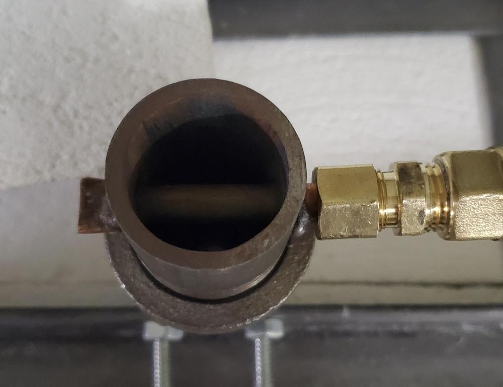
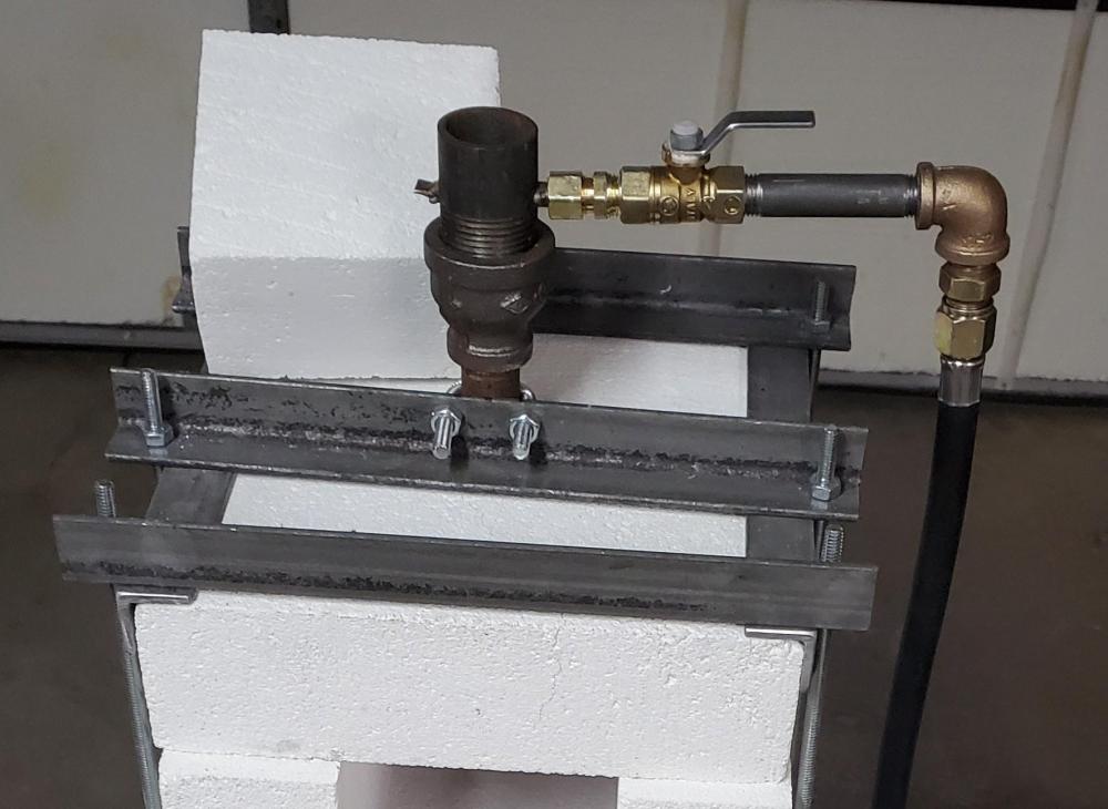
Here is a brief write-up with photos of how I built the injector for my 1/2" burner. Nothing real special and I didn't change the fundamental design in any way, Frosty has already optimized the design and function, but this is the tooling and tricks i used to drill out the T and fit a mig tip given the tools and materials i had available. There are two places during construction where people are most likely to run into errors that result in off-centered mig tips not pointing directly down the center of the burner tube. This does require access to a drill press. Frosty recommends using a floor flange and close nipple to support, clamp and align the T most easily. I agree with that but found my store has pretty low quality floor flange, T's and other fittings that are not always cast or machined so well. The floor flanges, for example, were not cast flat enough to rest solid on a surface nor were most tapped perpendicular to the base. I decided to come up with a way that would bypass those issues, hopefully. The second issue I found was no access to schedule 80 pipe fittings, meaning i could not find fittings with small enough internal sizes nor with enough brass/steel in the wall to drill and tap for the mig tip threads. I solved this by using a brass street elbow. By incorporating brass fittings, which do cost a touch more but that are machined to size the tolerances are greatly improved. Having a top mounted burner in a brick pile forge I wanted to move the propane hose connection to the side, hence I used a 1/8" brass street elbow. Street fittings have one male and one female fitting, usually but not always, in the same size/thread. I already had a 1/8 NPT (national pipe thread) tap so using the street gave me an inside diameter with plenty of wall thickness suitable to be taped for the 1/4"-20 threads on the Lincoln Mig tips i am using. * Note, different welder manufacturers utilize a variety of thread pitches including 1/4-20, 1/4-27, 1/4-28 and various metric sizes. Make sure you have the correct tap, pilot drill, etc to fit your particular tips. This has already been discussed in depth in other threads. As for the brass or steel fitting you use to insert into the T and hold the mig tip, use whatever style you need that will fit your setup and allow you to eventually connect gas. A street elbow is cast before it is threaded with a die so it is not the best choice. I picked through the pile to find one that seemed to have the cast hole as close to center in the threads as I could and with careful alignment before drilling and tapping it worked fine. My idea choice would have been a straight brass fitting, which are machined, but I went with what I had. Note, i did use a belt sander (or use a file) to cut back the end of the street a couple threads this got rid of any burrs and created a better surface to start driling an taping, and provides a better seat for the mig tip later. You want this surface flat, square and smooth! The biggest "trick" to all this is finding ways to index your critical surfaces with the chuck of your drill press, as you will see below. Here is a photo of all the fittings and main tools I used for this, plus a drill press and some wrenches. Now here is my first trick. Since we want our mig tip centered perfectly in the outer male threads of the 1/8" street elbow i will use the 2" nipple from my build plus an extra 1/'8 coupler. A brass coupler is more likely to be manufactured better but this one worked. By chucking the nipple in an UNPLUGGED drill press (you'd be amazed how much muscle memory makes you want to turn it on!) you can use it to carefully tighten the vise (you can use any clamping arrangement needed to make this work, including using angle clamped to the fitting the clamped to the table but these vises are cheap and very handy) then clamp or bolt down the vise. Careful patience here will keep everything lined up tight and straight. you can turn the quill by hand to back out the fittings leaving the elbow firmly clamped, then move them back down and turn my hand watching for run-out to ensure everything was tightened inline and didn't shift. And deviation try again until it is correct! Now remove the coupler and nipple and put in your drill bit sized appropriately for the tap for your mig tip threads. In my case it is a #7 for the 1/4-20 threads on the Lincoln tips. As you are machining very soft brass for only a short distance you don't need a number 7, a 13/64 is certainly close enough. Keep in mind you will need to change out the drill bit then but in a shorter tap,. all without moving the drill press table so play around with how down you have the quill when you clamp the fitting into the vise so you have room to do everything in one shot. Then drill out the interior of the fitting until you get almost to the internal bend, remove the drill bit, unplug the machine, put in the tap, and use the quill, turned by hand, with gentle and steady downward pressure on the handle to turn in the tap cutting the threads,. follow proper threading technique using lubricant and backing off frequently to break the chip, until you have threaded though the fitting. Read up on that if you do not know how. You will want to try the tip in the fitting before removing it from the vise to ensure you tapped far enough. Remember the taps are tapered toward the end to facilitate starting. Tap several threads longer than you need to be safe and to give you room for adjustment later. First part done! Notice how the mig tip seats tightly and square because I squared off the end of the street earlier. Now, using the same trick of indexing the important surfaces using the quill of the drill press, we are going to use a brass 3/8"hose to 1/2"NPT as an alignment jig. Above you see me drilling also. I messed up here and forgot to take an image of a key step!!! The real trick is to put the barb in the drill drill press quill, plunge down and lock in a vise and lock the vise to the table, then chuck up a drill bit that is just barely bigger than the inside diameter of the barb, and drill out the barb first. This allows the barb to act as a bushing also during drilling allowing the bit to wander less and start better against the rough and rounded inner surface of the T. All of this work is pointless if the bit wanders off center. By doing all of this we are helping to ensure that the hole in the T is lined up perfectly with the burner tube threads, which will ensure a centered mig tip and a better functioning burner. This also helps us align the T more accurately in a future step. After you drill out the barb, put the barb into the T, place it in the unplugged drill press chuck, move it down to the vise, tighten, lock down the vise, double check everything, release the chuck and insert the drill bit you just used. You may need a dry run here ,depending on how much travel you have in your quill, to have enough room to drill the T and also get the bit into the chuck. I have a tiny tabletop drill press and was able to just do it. Slowly drill the hole, starting gentle to help keep the bit from wandering or binding on the uneven, curved inner surface of the T, as shown above. Finally, we need to tap the T for the 1/8"NPT but we must do that from the outside, as they are tapered threads. Since we drilled out the barb fitting and it is inline with the hole and is all the same size, we have a convenient way to index this after we move it. Remove everything from the vise. Unplug the machine,. flip the T and barb over and slip them onto the drill bit still in the machine. Push the quill almost all the way down and lock the barb hex into the vise, lock down the vise. Make sure nothing moved when you were locking it down, switch to a letter Q or 21/64" drill bit (the required size for a 1/8"NPT tap) and drill out the hole form the top. ! Now unplug the machine, insert the tap and turn the quill by hand to tap perfectly straight and centered threads!
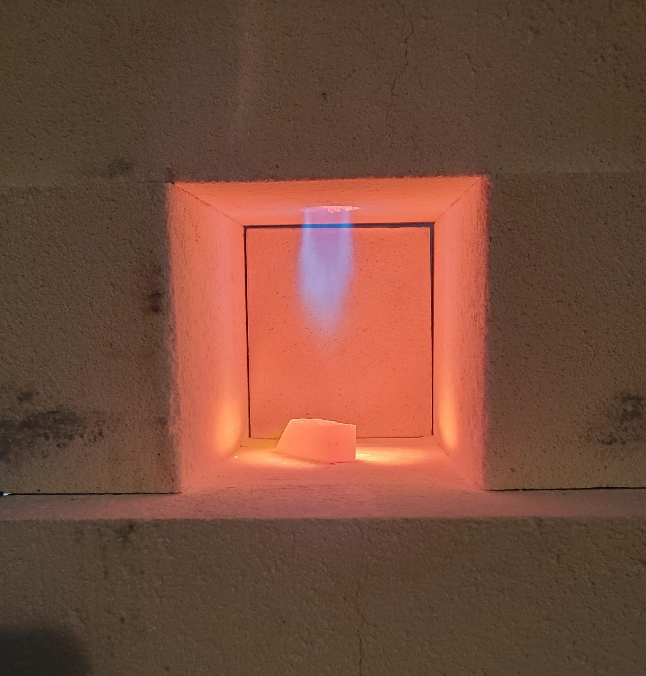
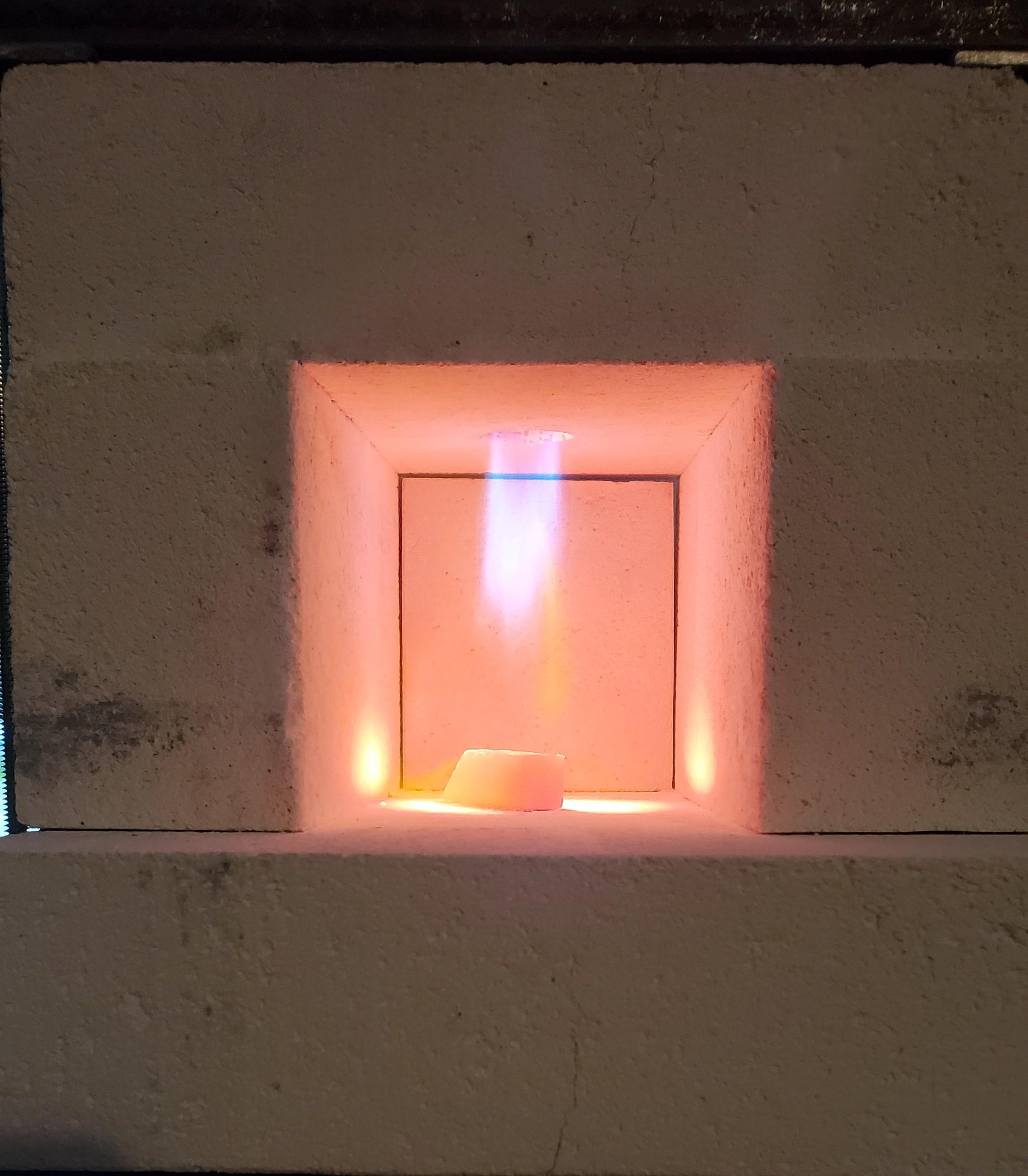
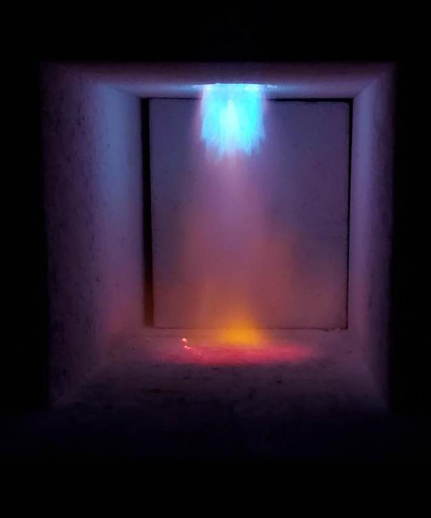
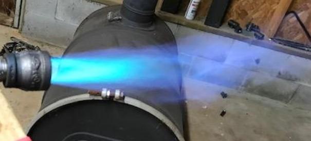
-
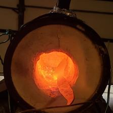
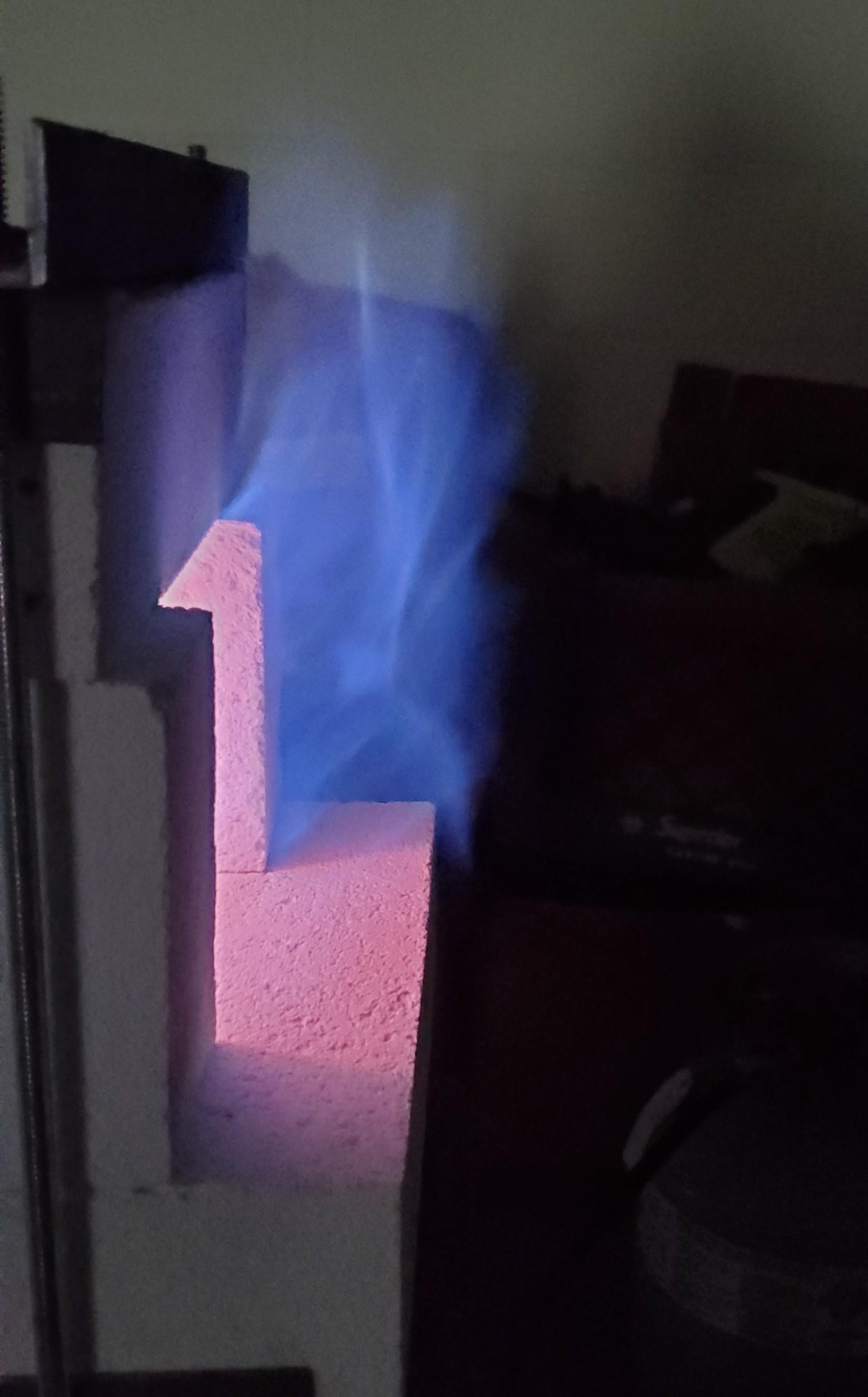
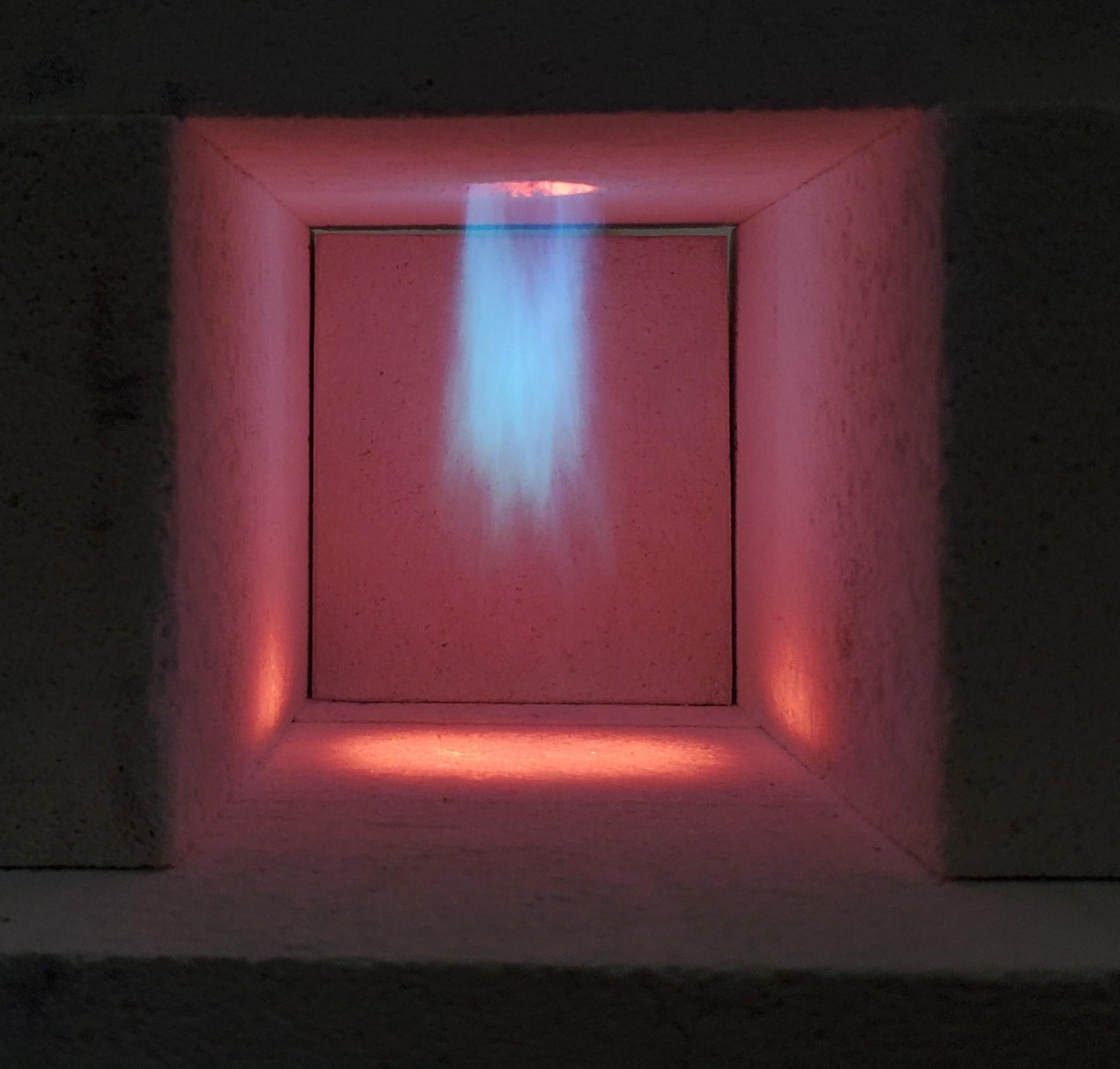
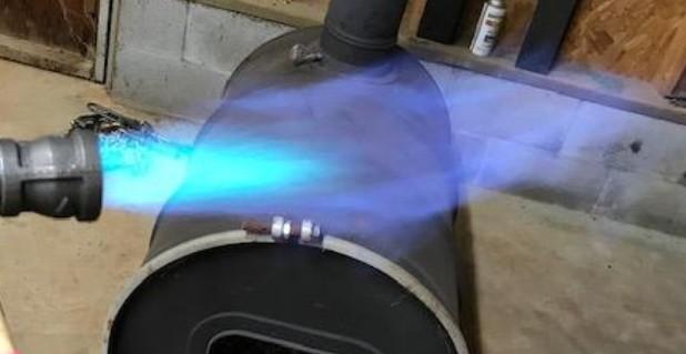
Update time. I've been able to work on this off and on over the last few days. I did start by taking Frosty's advice and move the injector tube down into the bell of the Reil style burner with no real difference. The was a slight improvement but still running rich. Since I considered it a failed experiment due to using a venturi opening that was too small I experimented by drilling more holes around the bell in the same plane. I drilled two, tested it, saw no improvement. Repeat, repeat. Finally decided the experiment was a good learning experience but that I could not improve the flame quality at all. As expected and in agreement with Mikey, I moved on. A call to my local autoparts store found they had 0.025 mig tips that Frosty recommended for a 1/2" T burner. Since i had to go to the hardware store to get parts to fix a faucet for my parents, figure it was time to try a Frosty T burner. I will update in this post with my resulting flame and in a following post i will show the steps i used to build the burner. I do feel this 1/2" Frosty T produces significantly better flame than my incorrectly constructed Reil style. That fault is on me, obviously. This being my only venture into burners I cannot and will not suggest that other style burners do not or cannot be made to work as well. I will say that with the limited tools i have available (though i do have a small, abused drill press with a touch of bearing play in the quill) the Reil was in some ways easier to get close, but with care and a few tricks the Frosty T can be constructed more accurately. The T is easier to get very wrong but with care you can also get it much better. That, plus the greater tune-ability of the Frosty T is a win in my opinion. That being said I've using tools like this for 30+ years.I So, the flame photos. Note, I cannot seem to get my cellphone to capture photos that are even close to the colors I see in person. These photos seem to have a lot of magenta and purple that I do not see in person. In person the bulk of the flame is a nice, bright light and dark blues reminiscent of the flame I have used in well functioning oxy/act brazing and cutting torches. This flame with just a little tuning has no green (I think Ive finally figured out how to identify that by examining flames that I know have to be very rich/reducing, though I do see it as a difference in blue at the tips rather than green due to my color vision issues), a rich blue color and occasional wisps of yellow. I have tried this burner with all manner of tip lengths in an attempt to better see and understand what various states of flame look like, starting at extreme rich/reducing using a full length mig tip and working my way back in 1/32-1/16 steps until the mig tip was almost gone resulting in a very lean/oxidizing flame. I figure sacrificing one tip was a worthwhile cost and I stand by that. A tip costs max $2 so it was money well spent. These photos are with the tip cut just past halfway (closer to the top of the T and further from the burner tube). Currently the tip is approx 1/32-1/16" shorter than half the opening distance. My method of construction (see my next posts soon) allows me to screw it in and out the up to +/_ 2/27" (thread pitch on a 1/8" NPT thread is 1 in 27). I've tried throughout this range and to my eye this best matches what I've seen the gurus here recommend, specifically Frosty where he has suggested tuning until just barely rich/reducing with no green and only minor wisps of orange in the flame and dragons breath. *Frosty, if I am misspeaking or have interpreted this incorrectly I apologize and am ready to be corrected.!* The first photo is within 1 minute of lighting the cold forge at approx 4-5 psi. I believe people say psi isn't the most useful measure but i like to provide as much info as possible both for myself in future readers (and my future self). Remember, this is a less accurate and lighter blue than in person but the proportions are similar and the occasional orange streaks are represented. Second photo is after approximately 2 minutes when its stabilized enough I could turn it up. This is around 8-10psi. Third photo as immediately after from the side. Note, in all of these the back is completely closed off. I suspect this is still running a touch rich, but too rich? Again, I am sorry for the poorly captured colors. I've spent a lot of time with nice camera equipment and editing software and not being able to capture reasonably accurate images is frustrating to no end. My good gear is 3000miles away :/ Out of curiosity I threw a 3" piece of stripped copper 12ga electric wire in the cold forge on a cold scrap of mild steel, light the forge, closed off most of the front door and running at approx. 10-12 psi the copper melted between 4 and 5 minutes. I know that Cu melts at approx 1980F. I also now know that 1980F mild steel and firebrick look like. Are there any other tricks like that I could use to learn temperatures/colors? I know nonmagnetic/Currie points for lower temperatures. Id like to find out if I can get to welding temps. Obviously I am a noob and that in some ways is an advanced technique but basic forge welds in mild steel seem like a necessary skill and I would love to someday try Damascus just cause. What are some approximates I should expect from a forge and burner this size to get to various temperatures? I completely understand that it all depends but I have absolutely no frame of reference. Should I expect a forge temp to hit, as an example, 2200F in 5, 10 or 15 minutes? Will I need to be at least at 10, 15 or 20psi? Will it never get there? Once i have an idea what to expect i can better associate my learning processes. Thanks again to reading and helping!

-
Not that I know much, but I hadn't realized there was such a difference in flame type. I really like this forum! I did notice that when I changed the position of the back brick the dragon breath largely went away. I didn't notice much difference in how the flame looked, but by then it was well heated and I couldn't see the flame as well anyway.
-
Another question I have... It seems most of the forges I see here have a larger pipe through which the burner is passed and various means of adjusting the burner in that setup. I drilled a hole though the brick that perfectly fits my burner, and tapered the inner about 3/4" to act as the flare having read on here that idea. But most of those other forges have a space around the burner. Seems to me that would act as a draft and allow more air to enter the forge at the burner nozzle. Is that correct? If I don't have that, am I limiting my air intake at the flame more than most, helping contribute to a fuel rich mix? Thanks Mike. That's basically the answer I was expecting. Boy oh boy do I miss my old lathe. It wasn't fancy but it was a lathe. Everything is so much easier with a full shop.
-
Unfortunately I'm in an incredibly rural place, and I say that knowing you are in Alaska! Ha! The nearest welding supply, steel supplier, and almost anything else is over an hour drive each way. There is a good hardware store just a few miles away though, and I know the owners (and my father worked there for a while after he retired) so I get the friends and family, plus I like to support local when possible. I know they only carry 0.030 and 0.035 tips, unfortunately. They are quite well stocked on black iron though so I know I can get whatever I need there for the rest of the build. To make sure I'm reading you right, my forge at 140ci is a little small for a half inch T setup, correct? But one can turn the 1/2 down enough to work. A 3/4 would be way to much in my small forge? Impatient me was hoping to get this running good tomorrow xxxx xxxx xx xxxx xxxxx. It's a curse, though one I try to fight..... I wonder if the auto parts store would have smaller tips? If not guess I'll be ordering online. I've seen your recommendation of 300-350 for the 3/4 T burner but I don't recall seeing a volume range for the 1/2 inch size. One reason I went with brick, aside from the crazy price I got them for (unopened case at 2$ per brick of the Jm30, 3000f bricks) is the ability to easily make it longer by half again or double if ever in want to. Just curios how far I could stretch 1/2" burner.
-
Quick question, is a 3/4 T burner on your b design too big for this forge? Inside is 4x4x8.5 so 136ci. If I can't get this working better easily tomorrow I will just get parts for a 3/4 T. I have to go to the hardware store anyway for something for my parent's house anyway. I know the smallest mig tips I can find locally are 0.03 (labeled size, not orifice) and I believe that is your recommendation for a 3/4 Frosty T. Thanks.
-
Friday, thank you for the kind words, explanations and advice. When I've got time to monkey with this tomorrow I'll try your suggestions and report back. Reading around the internet the last few days I've seen many of your posts so with folks like you, Mikey and the rest I feel like I'm an apprentice again (I was a furniture make and did a very traditional apprenticeship to learn). That's a great thing, thank you all!
-
Great, thank you!
-
Thank you!
-
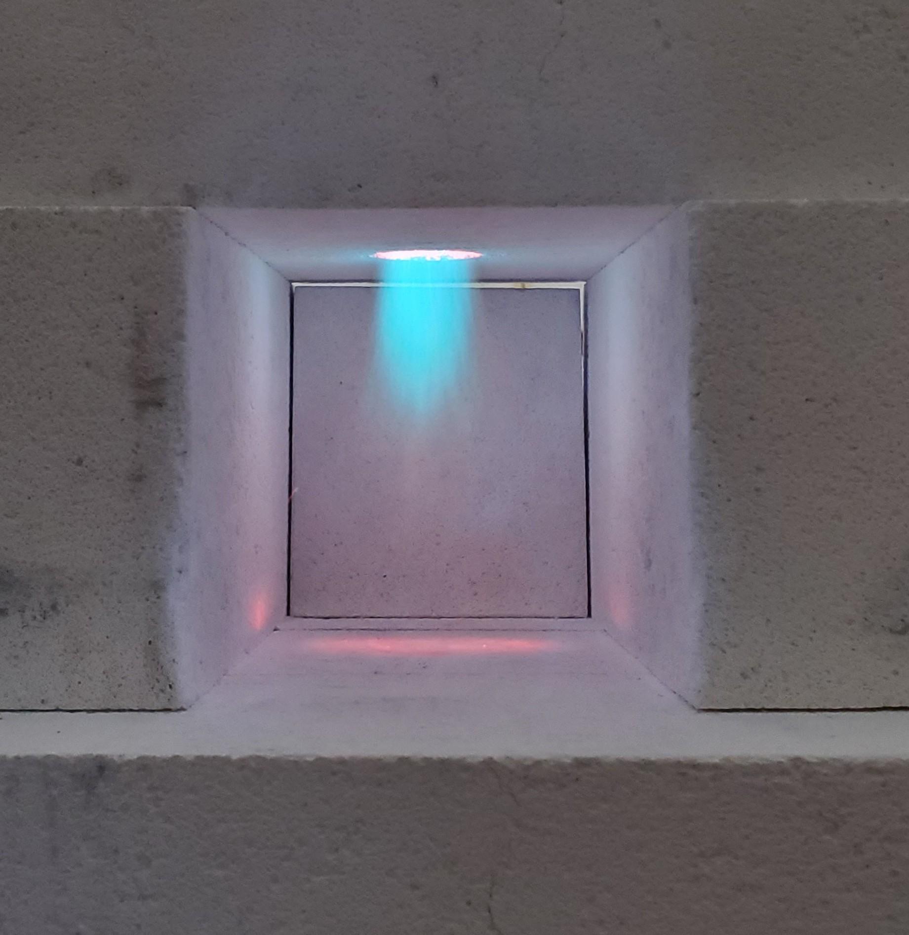
Thank you Binesman, for the reply! I've attached two photos. I made this before I found this site or had done much reading and as a result I think my venturi bell is too small. That should lead to a rich flame, correct? I used a 1/2" burner tube which is cut to 4 inches long. Then a 1/2"to 1" reducer and a short pice of 1" as the inlet. I suspect I should have used 1-1/4" but I already had all those parts in the garage so I went for it. My orifice is drilled into the side of 1/4 copper tube that has the end crimped and soldered. I used water from a hose to align the orifice with the center of the burner tube, then soldered it in place. The orifice was made with a 0.03 drill. It may be a hair bigger if there was runout, I have no way of measuring further. Here in lies me problem, in neither real life or in the photos can I see any green. I believe you, I just can't see it. What about the dragons breath suggests rich? More green color? Something else? I thought a rich condition there was signified by a strong yellow in the dragons breath... Not from experience, from reading, obviously. Thanks again.
-
Panik, I hope you don't mind but in an effort to learn I've grabbed your last two flame images and cropped them for comparison. I'm trying to see the differences and having them side by side and cropped helps. I'm hopeful that one/some of the knowledgeable folks here could take a moment and point out what they are seeing and compare between the two. What I see is that the second, improved flame has a smaller tertiary part that is "more solid" than the first flame. I see the secondary envelope as being more robust also, with a wider and more consistent tip on the second. I also see, again on the second, a more dense primary flame, like a pencil tip, that is solid all the way through as opposed to hollow in the middle right as it exits the burner flare. I'll admit that was easier to see once cropped it and ran thru my default "filters". Changing saturation and color let me pick out the different parts more easily on the original flames. These photos I've reattached are simply cropped, no color changes done.
-
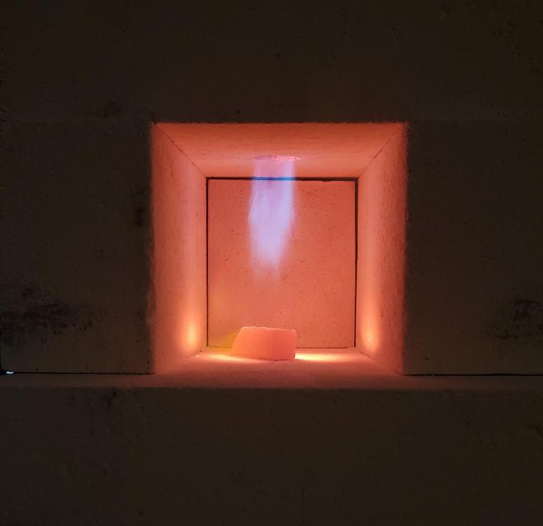
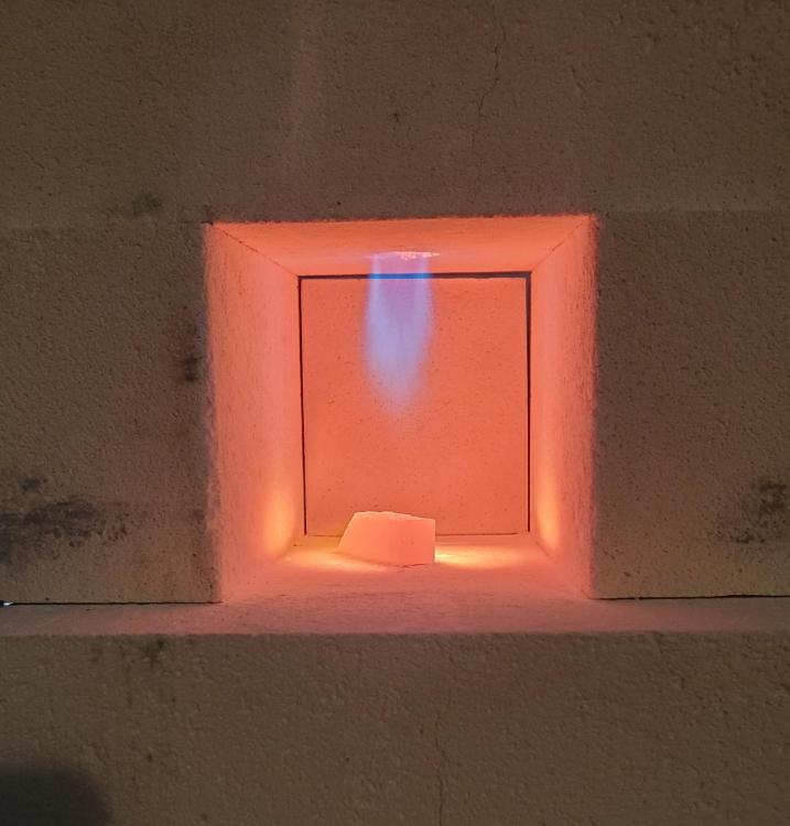
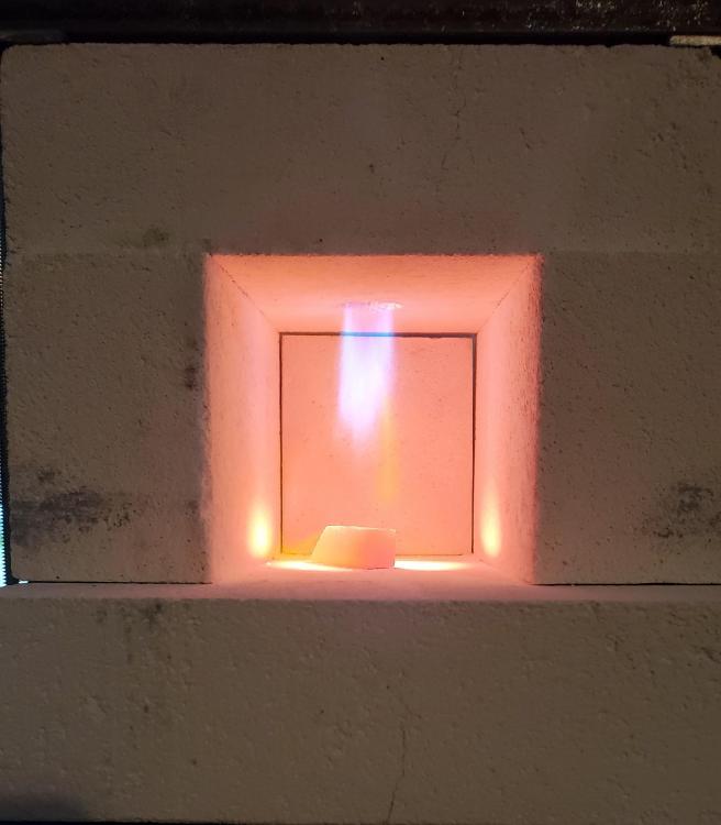
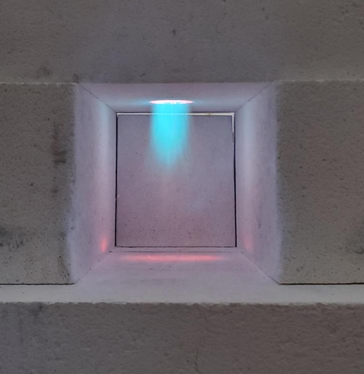
Thank you Mike! I've been lurking and reading here for the past week. I downloaded your book also and very well done and written! Only copies I was finding to buy were very expensive and I've read you mention to others how easy it was to find and download that I took that as acceptable to do. I got that's ok. If you know a source that isn't close to 100 bucks, I'd be happy to buy one! Again, thanks for chiming in and for the wealth of knowledge you have shared. Just adjusted a few things a bit on the burner, mainly adjusted it more vertical (it was pointing a hair left in the clamp before) and smoothed out a slightly tapered flare in the brick to act as burner flare trying to follow the 1:12 taper I've seen you, Frosty and others recommend. The end of the burner is set about 1inch into the brick measured from the inside forge chamber face, which is also where the taper begins. I had previously smoothed down, rounding and lightly tapering, all the inside edges of the venturi bell the step in the reducing side of the bell and both ends of the burner pipe. Each detail did seem to add a minute improvement, whether it mattered I don't know, haha. I'm attaching a couple images from just now. The first two (lighter) are within a minute of lighting it, running (I estimate) 4-5psi. The second two are after warming up about 4 minutes in a darker space. That has a higher psi, approx 6-8psi. After that I threw a full size rail road spike in and closed half the front off with a brick. It got up to non magnetic within 3 minutes. Pretty happy but I'm trying to learn both how to judge color and temp better and trying to optimize this setup as much as possible. Looking forward to continuing to learn here. Thanks again!


-
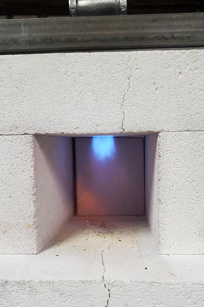
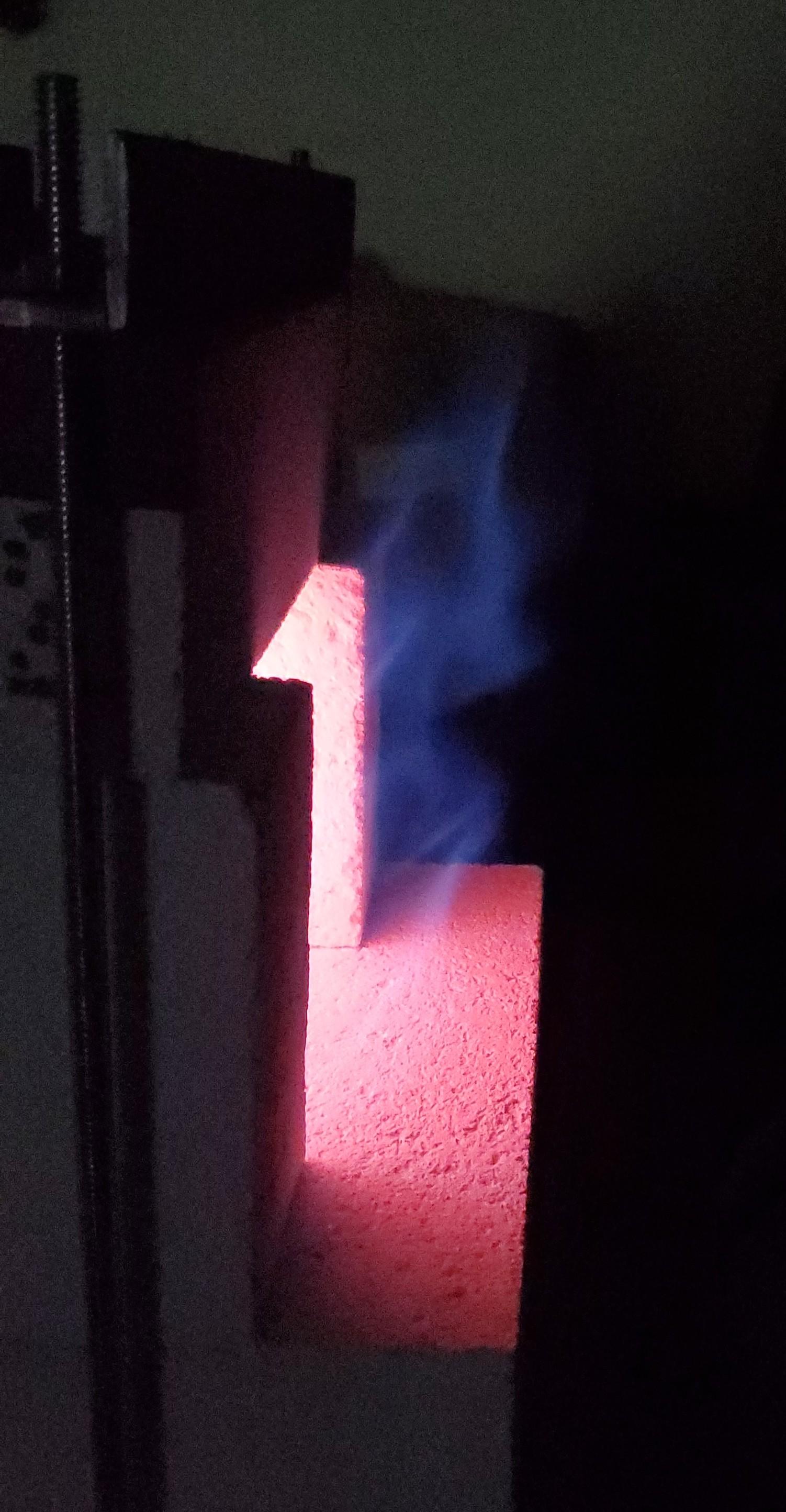
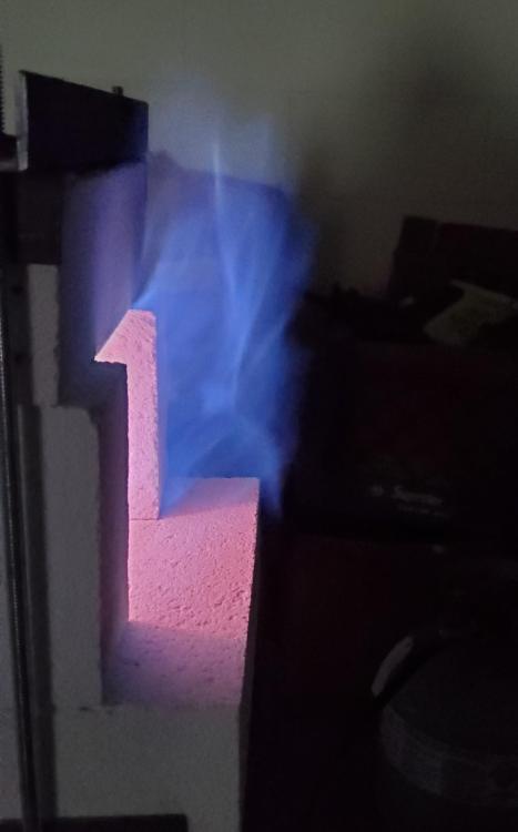
I know this is posted frequently, but I struggle with colors. I see all the primary colors but don't see shades very well. Anyway, I'm new to propane forges (forges in general actually) and I'm trying to learn. Using Thermal Ceramics JM30 3000f firebrick pile (approx 145 cu in) with a single 1/2" Reil style burner. I built the burner before I had read much admittedly but it is to general specs in fitting sizes and lengths. Using a 0.03 inch orifice (not mig tip sizing but actual orifice size). I feel like this is running a little rich but again, I struggle with color. I can't see any green, though green is very hard for me to see in general. Once warmed up the flame seems steady. I tried to take photos that represent what I see looking into the forge in a mostly dark shop. I did try to take photos at slightly different exposures. This is after about 5 minutes running. The piece of railroad spike was nonmagnetic immediately after these photos. The first photo is most like what I see in person. Dragon's breath is not real big, 4-5 inches at most and more orange than anything. That's really hard for me to see and I couldn't get a photo, sorry. Using an adj pressure regulator, no gage yet (on the way), but estimate between 5 and 10psi. Any opinions welcome and thanks for having me on this great forum!