peylas
-
Posts
2 -
Joined
-
Last visited
-
connecting a single phase motor to UK AC mains
peylas replied to peylas's topic in Machinery General Discussions
Dear Sir, Thank you for your help with my enquiry. I was obviously under the misconception that IFI was a forum for all: novices, experienced persons, and experts alike. And whilst I may have many decades experience in various crafting fields, including mechanics, metalwork, computing and so forth, elec-trickery continues to elude me. Combined with the varying and often contradictory advice given on the web, I thought I would seek help from a forum such as this, rather than destroy a not inexpensive new motor. However, I realise my mistake if this is a forum for people who should already know the answer to their own question, and as I had not appreciated that arrogance was another requisite, then I am certainly in over my head, and respectfully withdraw my enquiry and registration. Have a nice day. -
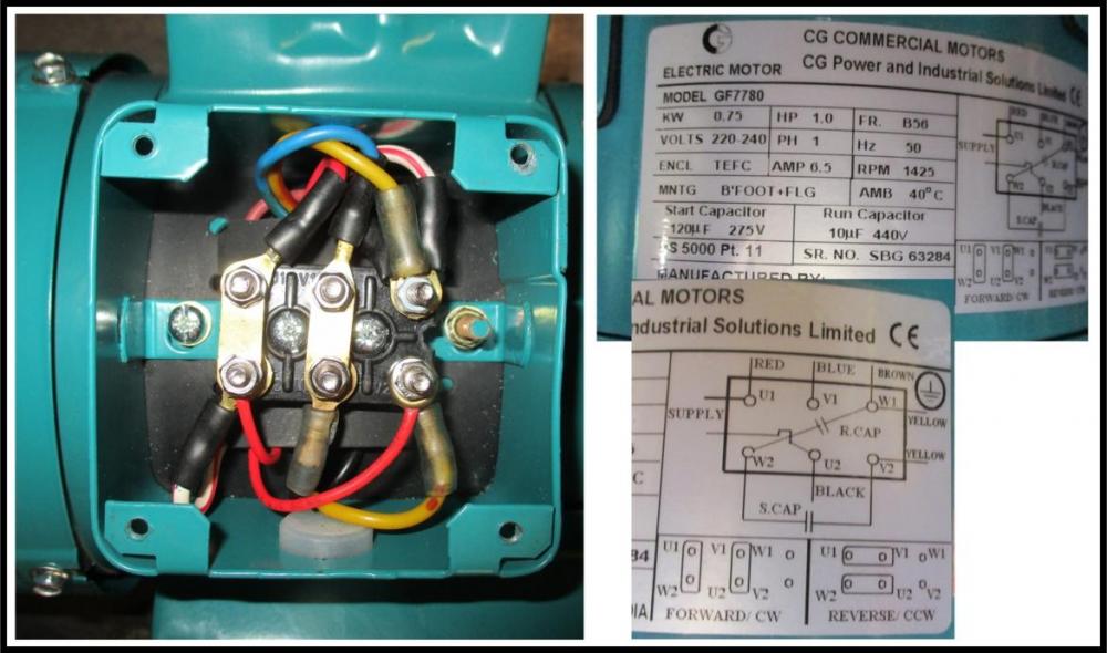
I have a single phase single volt (UK 220-240) 1Hp electric motor with two capacitors, start and run. As photographed. This is to run my Milling machine. I need to connect the motor, via appropriate switch gear, to mains AC. I appreciate the earth wire connects to the "seventh" terminal at the side. But I have no idea where the Live and Neutral wires need to connect. I appreciate that the metal strips (as photographed, shown between U1/W2 and V1/U2) manage the rotation, and presently are connected for forward/clockwise rotation, and can be changed to U1/V1 and W2/U2 for reverse/counter-clockwise rotation (which I will probably use). But for either scenario (CW or CCW), to which of the terminals should the Live and Neutral AC wires be connected? If someone could offer a clear answer please - in terms of U1 etc as per photograph - as I've scoured the internet and have fried my brain looking at too many conflicting options (mostly involving 3phase despite specific search criteria).