

St.patty
-
Posts
19 -
Joined
-
Last visited
Content Type
Profiles
Forums
Articles
Gallery
Downloads
Events
Posts posted by St.patty
-
-
So, I had to look up what an mpa is, not gonna lie. If my conversion-fu is working that works out to about 14 psi.
I am just as new as you are to all this, but, for what it's worth my forge runs happiest at 4 or 5 psi (.027-.033 mpa, again assuming correct conversion) and that's on 2 1/2" burners.
Long story short I suspect your psi may be a touch high, but if I were you I'd wait on one of the old salts here to confirm or deny, please dont change anything just based on my word alone.
-
Okay thanks, hadnt known that. I already have some refractory so today I will get on making a floor in it.
-
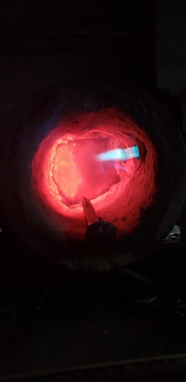
So would you not recommend putting a fire brick in for the "floor"? That was my plan, and when I get said fire bricks I will be building the wall as well; for now I have a crude lid that I have been using to get the heat up.
As far as rotating you mean have the burners vertically oriented and on top? I had considered it but was worried about losing too much heat from the burner openings.
Edit: picture was taken at 4 psi after ~4 minutes of burn time.
-
In keeping with the other guys who have recently finished theirs, I do believe I'm done. What do yall think?
This was my attempt at 2 1/2 Frosty Ts spaced evenly through the forge body. It's a "cylinder" that measures roughly 10" deep by 7" diameter.
Ignore the railroad spike that's just something I was heating up while testing so I didnt feel like I was burning propane for funsies.
-
Those look eerily similar to the ones I just finished up, but mine were 1/2" tubes and had a couple other differences. I decided to stop posting so much about it and start just doing more, and tonight I finally started putting refractory on.
Just my .02 here, Ill throw it in with the "listen to Mikey" crowd. Frankly I'm suprised he still has patience for new guys like us.
Good luck with your build!
-
16 hours ago, BIGGUNDOCTOR said:
Care to elaborate? I'm no electrician but I have quite a few 3 phase motors around, just havent been able to concoct a way to make them work.
-
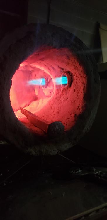
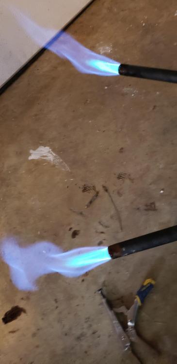
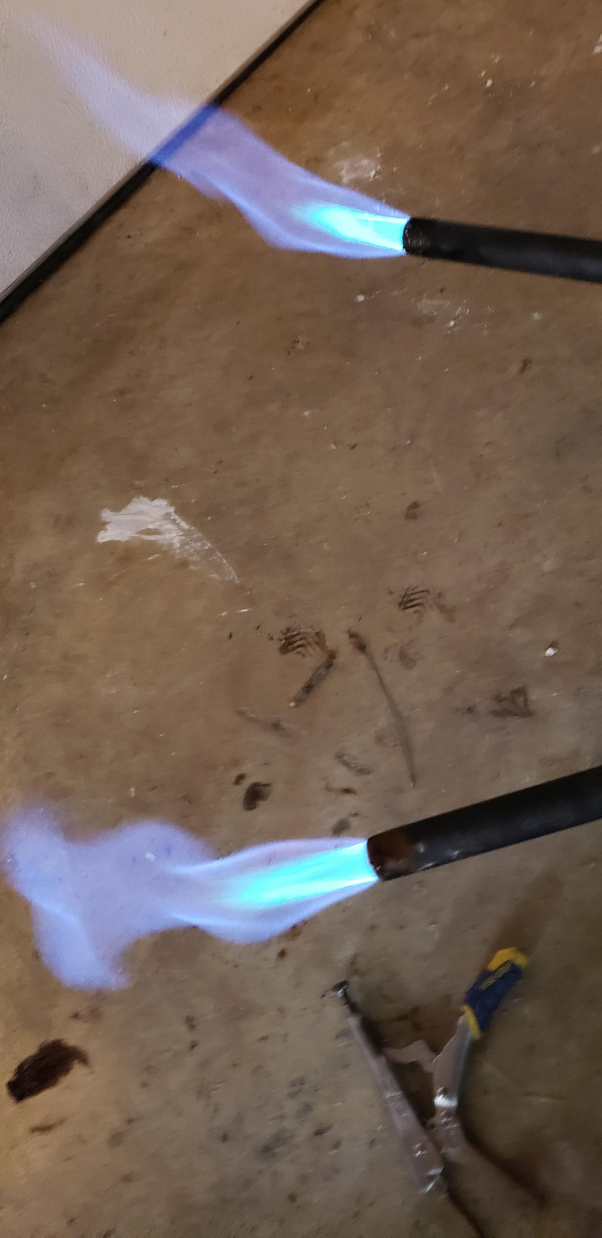
Alright, another day, another update I guess. I only had the time to get this one picture while they were running but! Following Mikey's advice, I made some sleeves for the back of the T and re-drilled them for the MIG tip to fit through, making sure it was aligned properly down the burner. Following that, I added on a couple of 3/4"x1/2" reducers i had laying around from my last attempt at this. I assume the holes in the sides of these are doing me no good, so they will be replaced shortly. When this picture was taken they were running somewhere around 6 PSI.
But just with these 2 modifications (moving the MIG tip pack to where it is only 3/8"" or so inside the T, and adding the cones) I THINK has gotten me a lot closer to a pair of real burners. Thoughts?
P.S. Im not sure why the two flames are so different, in theory they should be the same, no? I will take a close look at them tomorrow for any minor differences I may have missed.
-
6 minutes ago, Mikey98118 said:
That would depend on the inside diameter of the fitting. This isn't my design. I have noted that the tip ends in successful "T" burners start out at a little over half way, and are then carefully filed back until they hit their "sweet spot" this is how this burner design is normally fine tuned. There is a mountain of information on "T" burner construction in that permanent thread.
Alright, I'll stop being stubborn and go read the whole thread then. Thanks again for your advice
-
Yep that's because they're not soldered in place yet, and this is why! I wanted to make sure I had it all dialed in before it's set forever. When lit, I can move them around and adjust a bit.
So you're saying the tip needs to be about 3/8" away from the outside wall of the T, right? I'll adjust and update. Thanks for all your help btw
-
13 hours ago, Mikey98118 said:
That is probably your main problem right there. The farther the point is from the opening the hotter this burner runs.
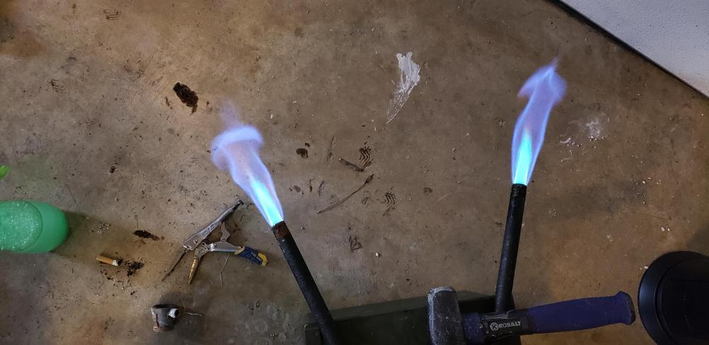
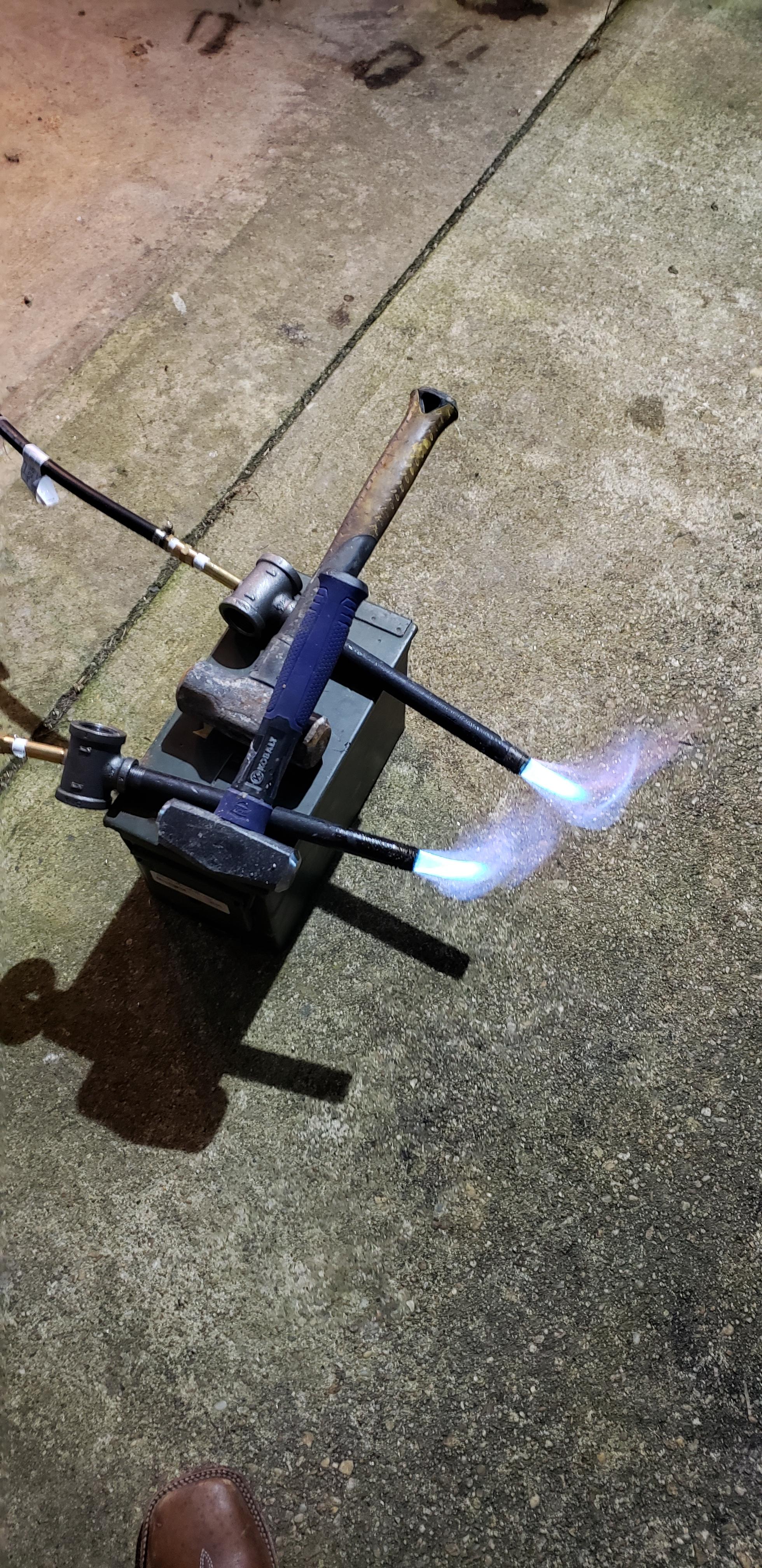
Okay! I have more pictures today.What i've done here is basically stick just the tip (heh) of the MIG tip inside the back end of the T, wrapped in kaowool just to be sure. in the picture with both burning, the one on the left is the one thats been modified, whereas the one on the right is the same as last night.
EDIT: Inside the garage this time with the door closed, so no more wind issues.
-
13 minutes ago, Mikey98118 said:
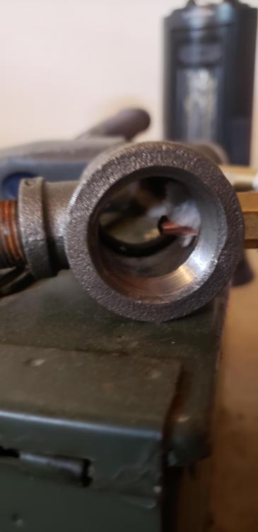
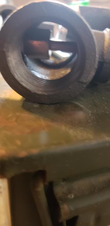
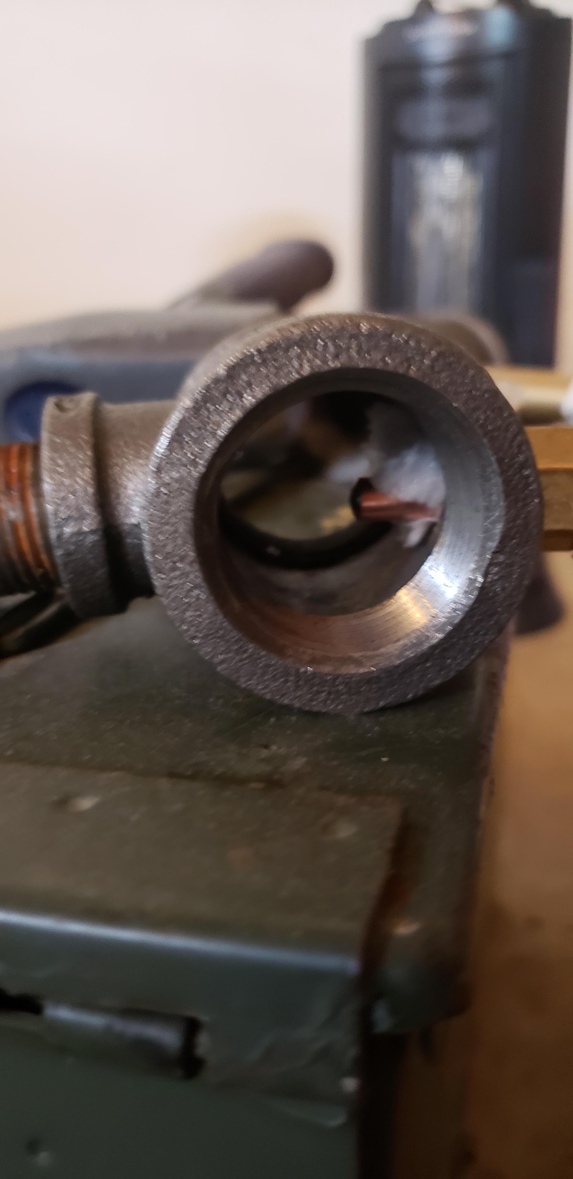
Well, no; those are NOT decent flames. They are so weak that they can exist out in the open air without flame retention nozzles. I'm sorry, but you need to spruce up those burners before you go any further, or you will be getting sick from carbon monoxide poisoning. Don't panic; we can coach you through the process You need to begin by taking close up photos of the "T" fittings in both directions. Then strip the mixing tubes and take a photo of each burner edge on so we can see how the MIG tip is located within them.
Well in their defence, that was outside and the wind had kicked up a bit, but I see what you mean.
The end of the MIG tip is right at the intersection of the T, maybe about 1/4" down the pipe. I figured that made for a decent spot.
I'll get the pictures tomorrow, thank you!
-
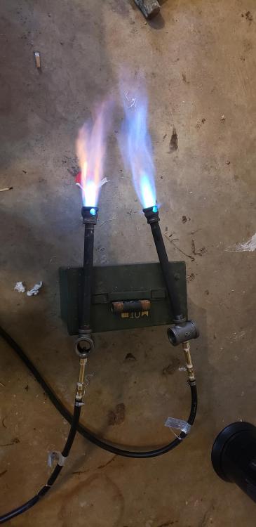
Okay! So I'm a little bit sorry for resurrecting a dead thread, but, back in the original there was some interest in seeing 1/2" burners...
To sum it up, i decided that rather than have 1 3/4" burner in the middle, i wanted to have 2 smaller, 1/2" ones offset, for (hopefully) more even heat distribution.
Well I'm posting tonight to tell you I've finally gotten them to work! What I ended up doing was:
- 1"x1"x1/2" T fitting, cast iron
- 8" long 1/2" iron pipe
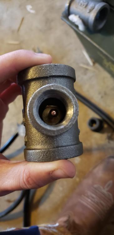
In the back end of the T fitting i drilled a hole out to 1/2" and then CAREFULLY bored it out further until I had the brass nipple sitting on the shoulder between the threads and the body (I plan to solder this properly later once it's all finalized) My forge tips are 1/4" x 2.5" long brass nipples, with a 1/4" cap on the end. In the cap I drilled and tapped a hole to fit a MIG welding tip (this was a 1/4" 28 TPI tap) and used a .023 MIG tip for my "injector" of propane. They lit right up on the first try! And from what I can tell it looks like I have a decent flame. Spray bottle of soapy water later and I did find 2 leaks, so I shut it down for the night- tomorrow I will be chasing down those leaks and sealing it all up. I've attached the only picture I managed to get before realizing I had leaks. Hopefully this helps someone who was looking at doing 1/2" burners, and if yall have any questions I'll be around!
**QUICK SHOUT OUT to all the people far smarter than me on this board, I leaned heavily on the math and knowledge here for everything I've done so far. Thanks!

-
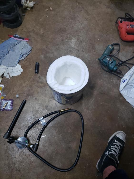
Got one end assembled and about to start drilling holes. This will be my forge body, it's now lined with 2" of ceramic wool I found a local supplier for (atlantech, for those of you who live in MD. They're in Elkridge.) Its rated for 2600 continuous use.
My remaining area is an 8" circle 9.5" deep- little smaller than what I wanted but it'll do. Time to go make my mold and pour.
-
7 minutes ago, Daswulf said:
What mess?
You'll see as the pictures go on, man. I've always kept a clean shop but I JUST moved in here so it's kind of a train wreck still.
-
Ignore the mess please.
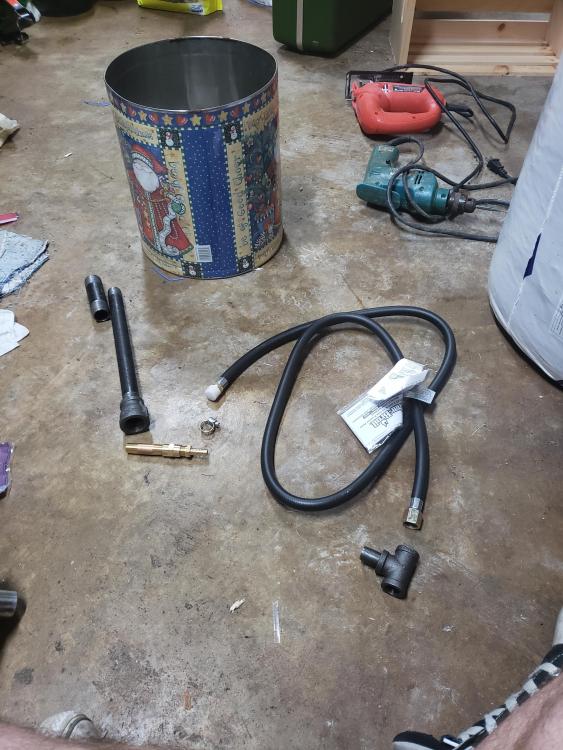
Alright guys, about to get started. Pic is of the parts for one burner, aside from the T near the camera, that's off the regulator- so the other burner assembly will start on the other side of the T.
It goes:
Regulator-3/8 nipple-3/8 T-gas grill hose.
This is where things got a little country, as the fittings I had were all pipe thread and the female end of a grill hose is SAE thread; I'll have to cut the female end off.
So from there it's a 5/16" Barb x 1/4 male fitting- 1/4 female coupling- 1/4" x 2" nipple then a 1/4" cap.
The rest is a 3/4-1/2 black pipe reducer and a 10" section of 1/2" pipe.
I'll check back periodically for questions or concerns, and for yall who have pitched in with advice so far thank you! I'd be so lost without this site.
-
10 minutes ago, ThomasPowers said:
Wayne Coe sells appropriate materials in reasonable quantities at reasonable prices. Have you read his build a gas forge page on his website yet?
Actually hadn't seen this, thanks!
If this is still around this weekend as I'm assembling burners I'll put up some pictures.
-
2 minutes ago, ThomasPowers said:
what you seem to be looking for is "castable refractory". Not knowing where in the world you are at I cannot make any suggestions on where to find it local to you.
Do you plan to have this inside the kaowool or outside the kaowool? Inside a thin layer acts as armouring against mechanical wear and damage; but is a heat sink decreasing the efficiency of the forge. Outside it doesn't add much to the forge if properly built than weight.
Sorry, I'm in southern MD. I'll update that.
I had planned for it inside the wool, to protect it as eventually I'd like to do some forge welding and I heard borax is awful for kaowool.
-
Hey all, I've been referencing this site a lot in recent weeks so I decided to go ahead and post.
To get to the point, I'm beginning my forge build this weekend. I put a twist on common designs I saw around and went with two smaller venturi style burners, with the idea of more even heat distribution. I'll put some pics up this weekend if theres any interest.
I've got my ceramic wool and my forge body, but I'd really like a cylindrical fire brick to help this heat distribution along more. Does anyone know where to get one, or have any input on making my own? I've seen about as many recipes for fire brick as there are members on this site.
Aside from that, any input or anything you guys learned the hard way, I'd love the advice. Learning all this on my own.
For the record I'm looking for my final size of heated area to be a 6" diameter cylinder, probably 18-24" long. I know that's a wide range but I can adjust as needed.


Help and tips requested
in Gas Forges
Posted
Yeah, from the scale of it I think our forges may be very similar in cubic inches. Mine is simply cylindrical rather than a rectangle, and has 2 small burners vice your 1 larger one.
At any rate, lots of wicked smart people here, I'm sure with some help from these guys you'll have it running like a top in no time. Good luck with (the last 10% of) your build!