Gavj75
-
Posts
67 -
Joined
-
Last visited
Content Type
Profiles
Forums
Articles
Gallery
Downloads
Events
Everything posted by Gavj75
-
Thanks very much for your help with this 'twar'. Your a star. I was given the motor a couple of years ago by a work buddy and didn't get any terminal bridges with it however, I can make a few from a piece of 0.5mm brass plate I have laying around so they should suffice. Clarke do still make motors like mine, so I sent them an email asking if they could help me with a wiring diagram for it. Unfortunately, I've not received a reply from them but thanks to you, I don't need one now. Thanks again twar Gav
-
 Love it. Hope mine works this well,lol(if I ever get it finished)
 -
Thats good to know"Buzz". Gives me a bit more confidence in my plan of attack. Just need the motor wiring problem sorting and I'll be at it. U any good with 240v electrics Buzz?
-
I kind of had an idea that that's what it was but wasn't sure so thanks 4 the explanation. Like the saying goes "you learn something everyday" Gav
-
I like the way you used a 1/4 rod to 180 your block over, so it lined up. I may well use this technique when I drill my block. I'll see how it goes. Gav P.s. What do u mean by "buttered the block" Sorry, " buttered the wood "
-
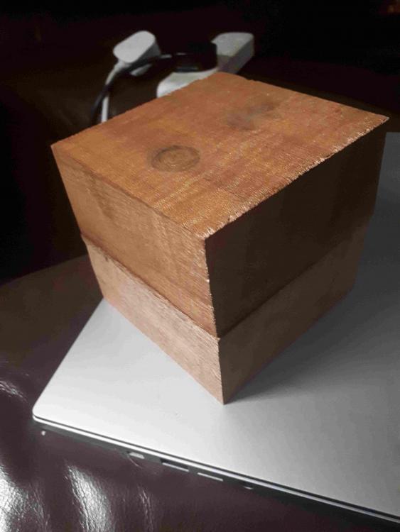
Yeah, I lined up the 2 chunks of wood with the grains running roughly at 90° to each other. Used PVA wood glue and left them clamped up for 24hours. Just need my motor wiring up now so I can crack on with it.
-
Unfortunately all my friends use hammers and gas-axe's for a living aside from one who's a joiner. Hence, I can't find anyone to help with this
-
Thats news 2 me Frosty, altho' I don't really understand the difference between 3 phase and single phase, I always thought its 240v single. Not exactly positive about that one cheif
-
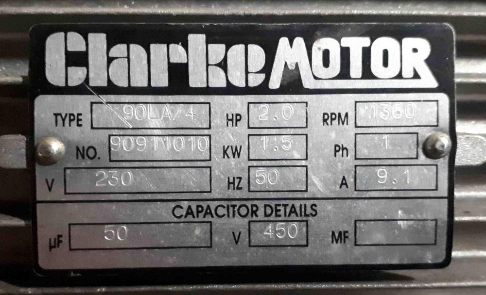
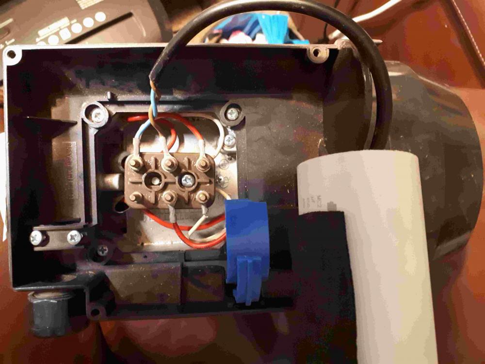
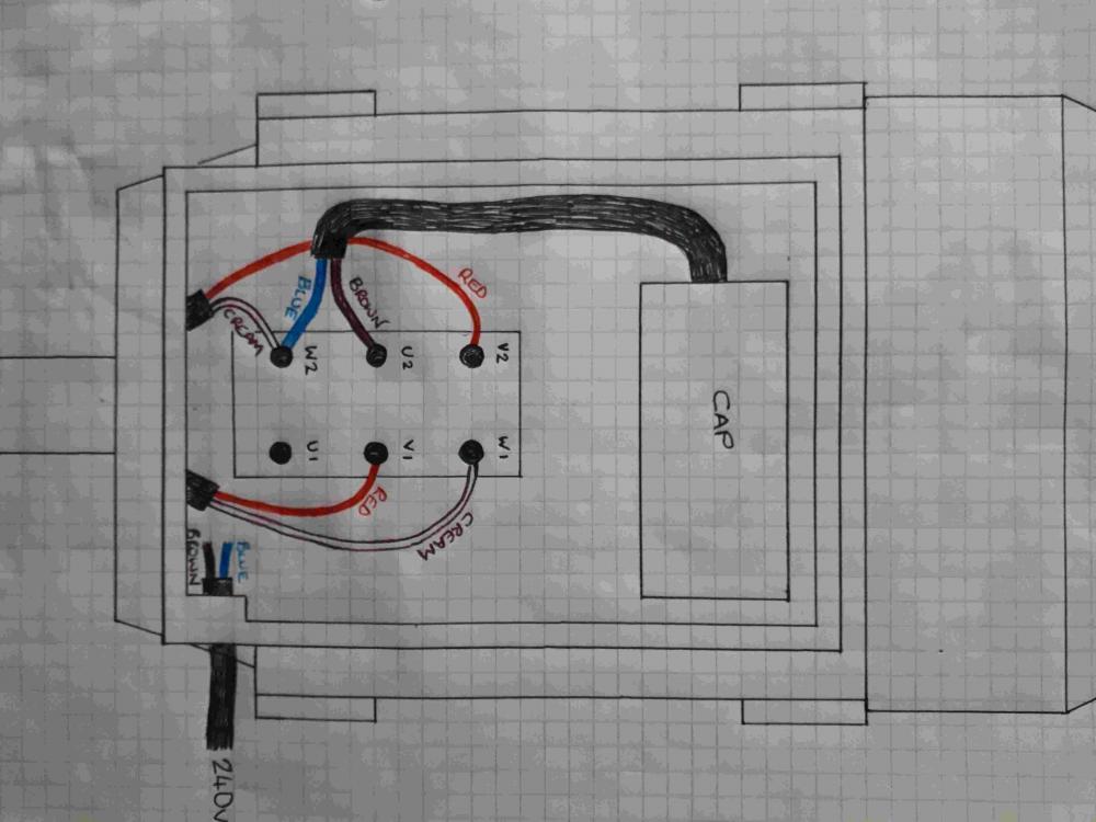
I really aren't sure which heading this should be under so opted to put it here. I have no experience of electrics apart from putting on a plug and paying the bill so hopefully someone can guide me with this. I need to wire up my single phase, 2hp motor with a 240v plug but have no clue at all. There are 6 terminals and a capacitor to consider and I've been told it's a relatively simple task. I've added a drawing of how the wires are connected on it in order so you can see it clearly and help explain it to me. I've tried looking this up online but could only find an explanation with 2 capacitor's attached to the motor so thought it best to seek out exactly what I need rather than try to interpret that. Thankyou in advance to anyone who can help. Gav
-
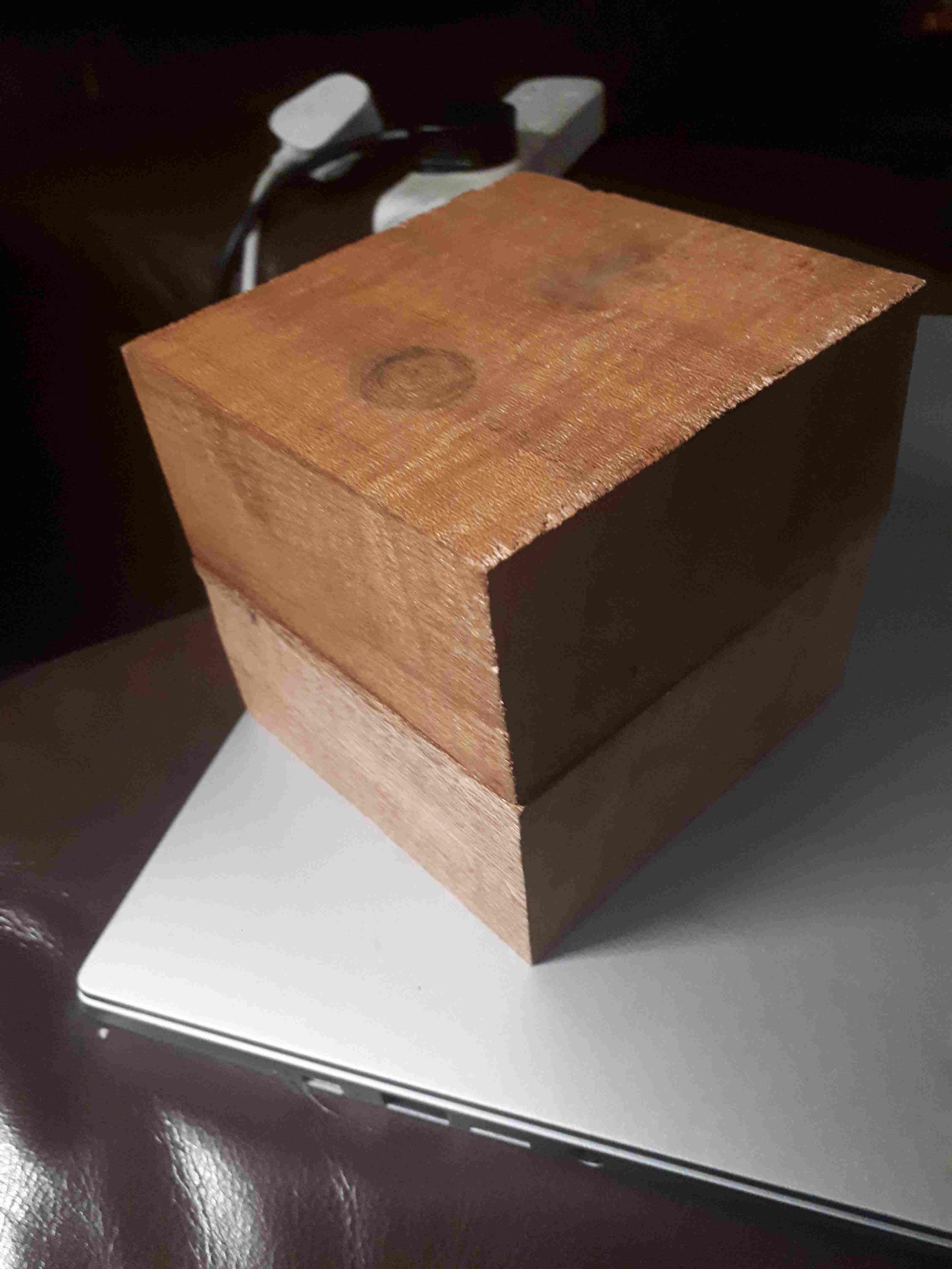
As soon as the anvil post is finished I've got the small problem of making my drive wheel. Getting one turned is definitely not an option as I was laid off from work last Friday, along with 30 other lads, so I now have even less money to spend on it than before. My idea is to make one from 2 bits of hard wood glued together to make a block roughly 4" × 4". It's teak apparently.I'm going to grind a 25mm wood drill bit down to 23.9mm, ish(the motor shaft is 24mm)then drill and attach the block to the motor. Then build an improvised wood lathe around that to turn the block into my wheel. Thats the plan anyway. I'll let you all know how it goes.
-
Hey Ted, I just wanted to say good luck with the build(altho' u've probs finished it now) and also that ive really enjoyed reading this thread. Im guessing your a bit like me in the fact that u like to experiment with your own idea's before copying somebody else's. What do u do for a living Ted?
-
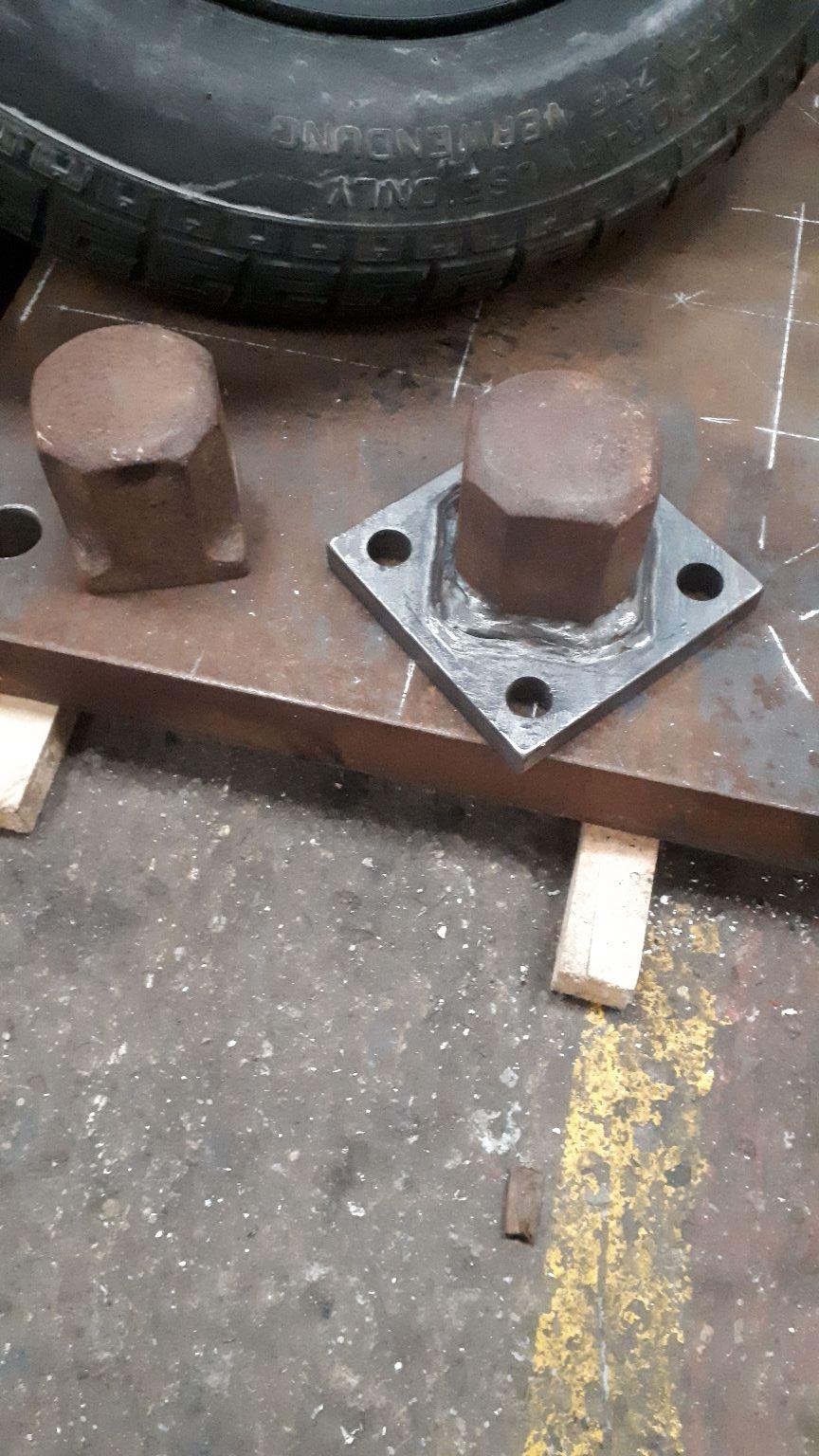
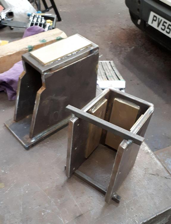
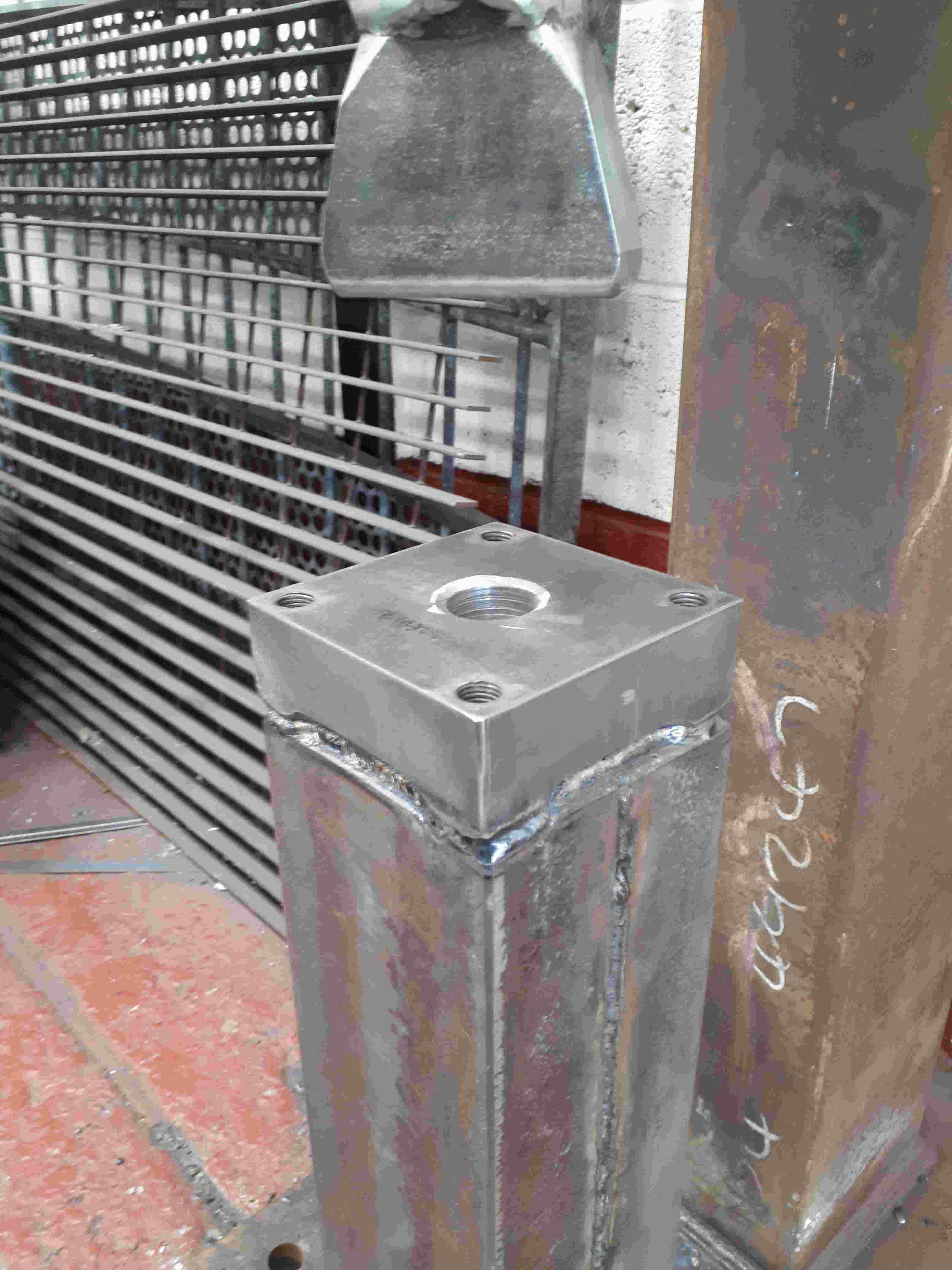
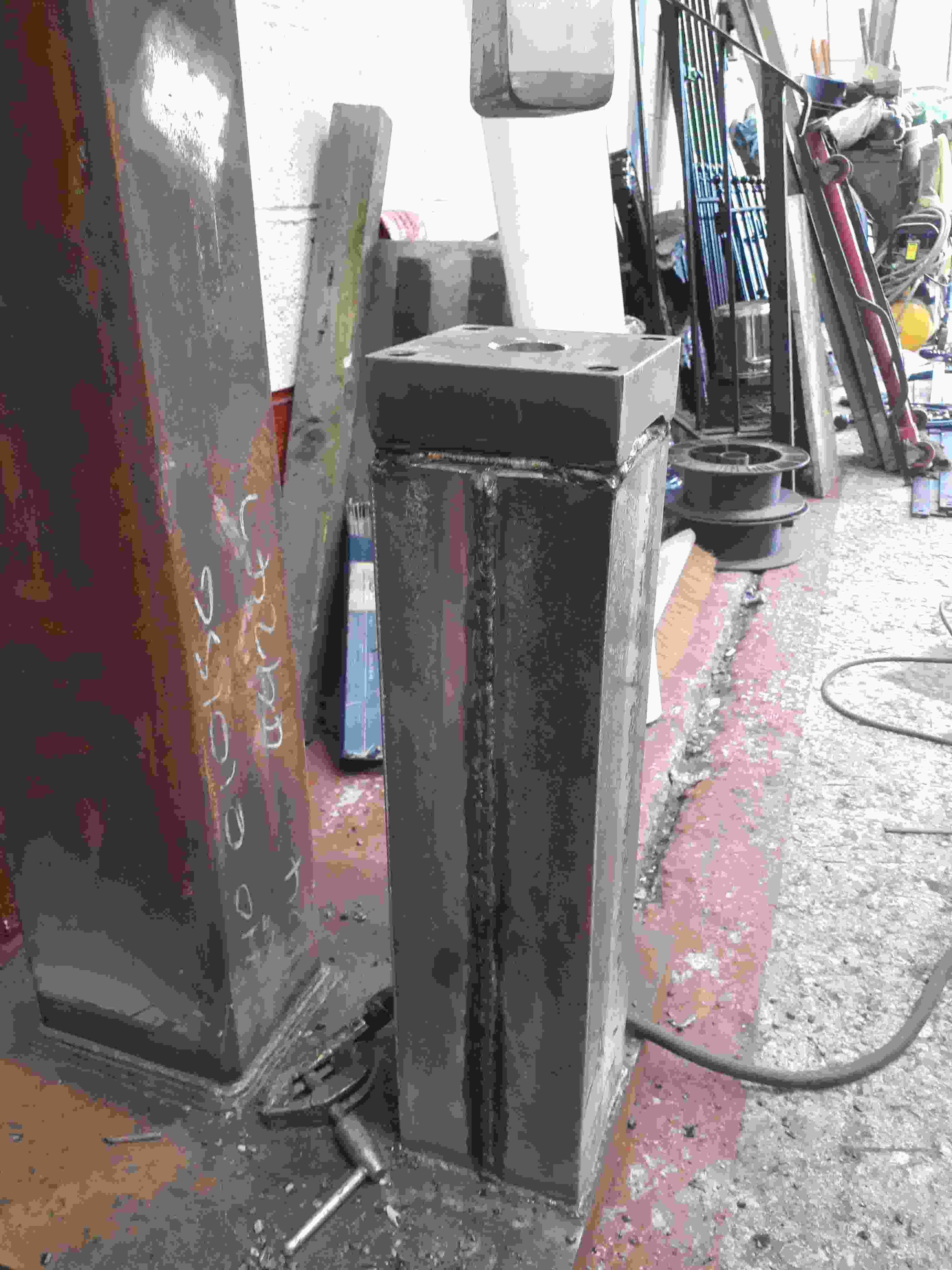
Just a couple of pic's of my anvil post (still not fully welded)for you all to check out. The hole in the middle is so I can weld it up and achieve, at least a small amount, of solid core material. With the equipment l have to work with, I think this is about as good as I can get. The pics
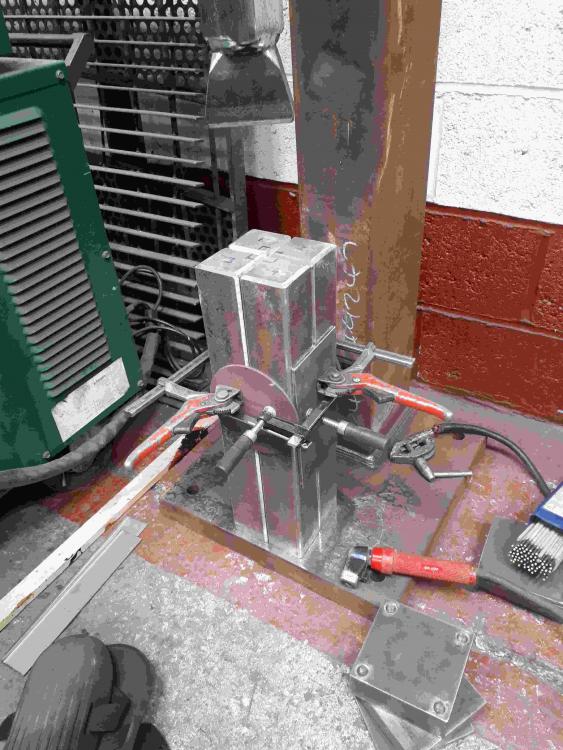
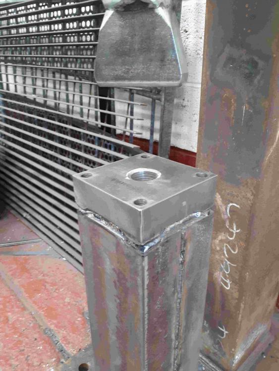
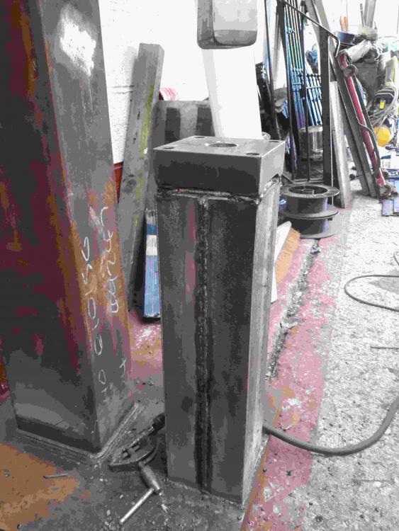
-
first trial towards forging a conrod
Gavj75 replied to BeaverNZ's topic in Power Hammers, Treadle Hammers, Olivers
Epic. Your obviously a very skilled chap indeed. I wish I had access to your toy cupboard -
 Love it. I bet these sell like hot cakes
 -
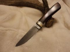 I hope I can achieve this kind of standard in time. Awesome knife, top notch.
 -
Yep, got you, read u loud and clear. It's not that I'm ignoring your advice FTL, and I do appreciate your input and guidance, it's more a case of as I don't have money to throw at the issues I come up against,and even if I did, I wouldn't, as well as the fact that I'm a mechanical engineer with 20+ years experience using heavy machinery and the fact that I started doing this because I enjoy designing and building things, that I'll be trying out my ideas before reverting to an alternate altogether. I have no interest in buying proven plans to build something from. That is pretty much what I do at work every day. There is no fun in that 4 me and if there's no fun, what is the point in the first place.
-
The contacting surfaces between the shaft of the hammer and the brass slides which are housed in the shaft sleeve have been a source of concern for me since I first put the assembly together. All my instincts have told me that I need to make it bigger so thanks, ''arftist'', for assuring me this is the case. I have an idea that I'm going to give a go, by adding some guiding rollers to the top and bottom of the sleeve, before I re-make the whole assembly. Who knows? you don't know until you give it a go, right? As for the bpm's, I was originally going to go for 150, 2.5 per second but decided to up it to 180 after reading the reply's I got. I'm now going to go with 150 again which is a 2.5inch diameter drive wheel. If this turns out to be too fast and possibly even scary, I can always drop it down some more by taking a bit more meat off my drive wheel. I can take more off but can't add more on. I didn't get much done in the shop again this week(I only get a few hours most sundays) apart from I built my anvil post. Its not fully welded yet and don't have any pics for you to see, but it's a bit more progress I spoze. Thanks again for everyone's feedback, untill next time
-
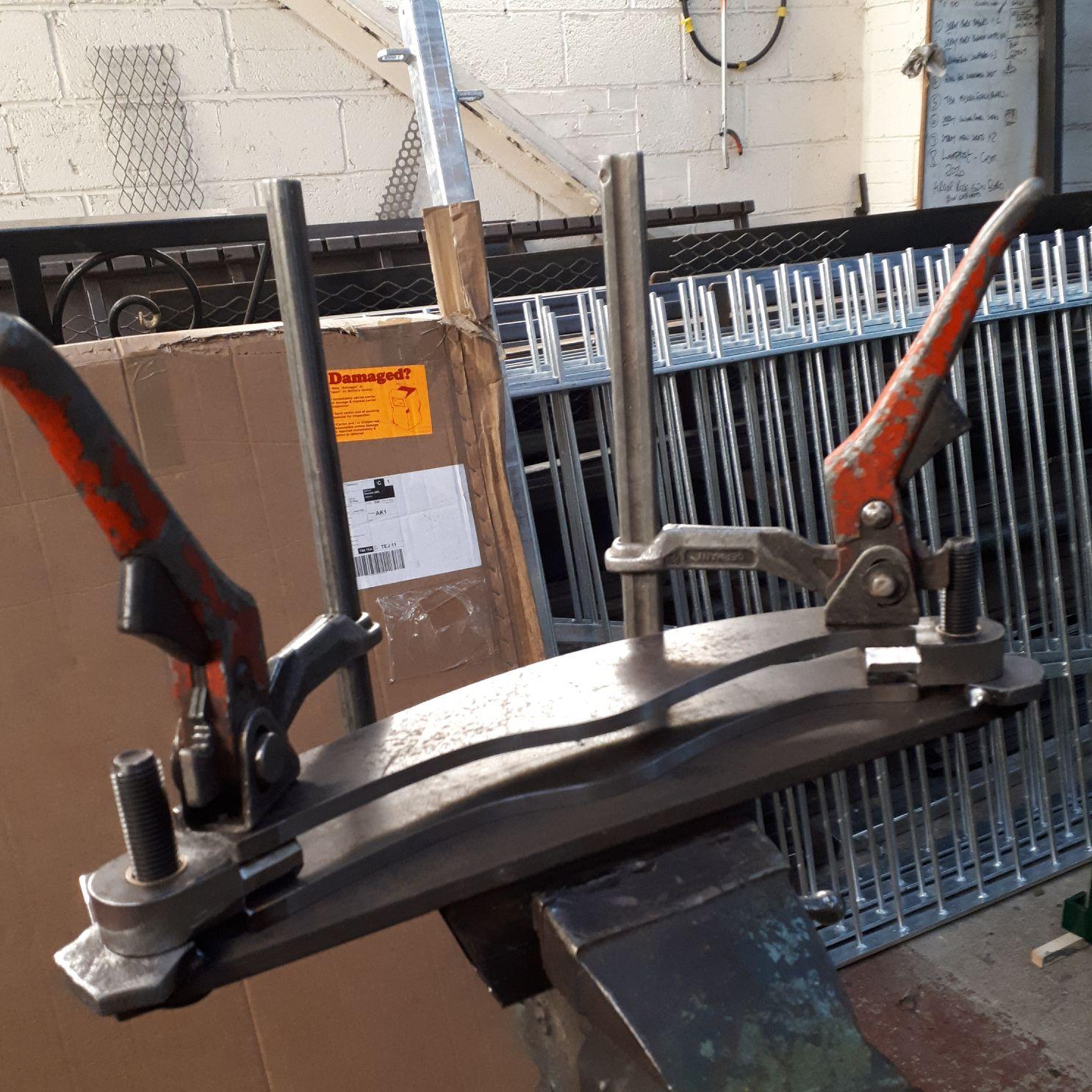
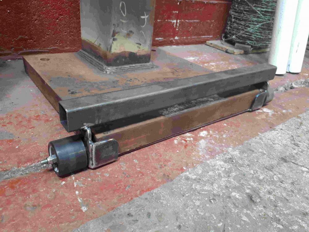
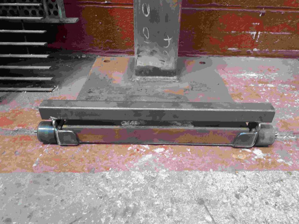
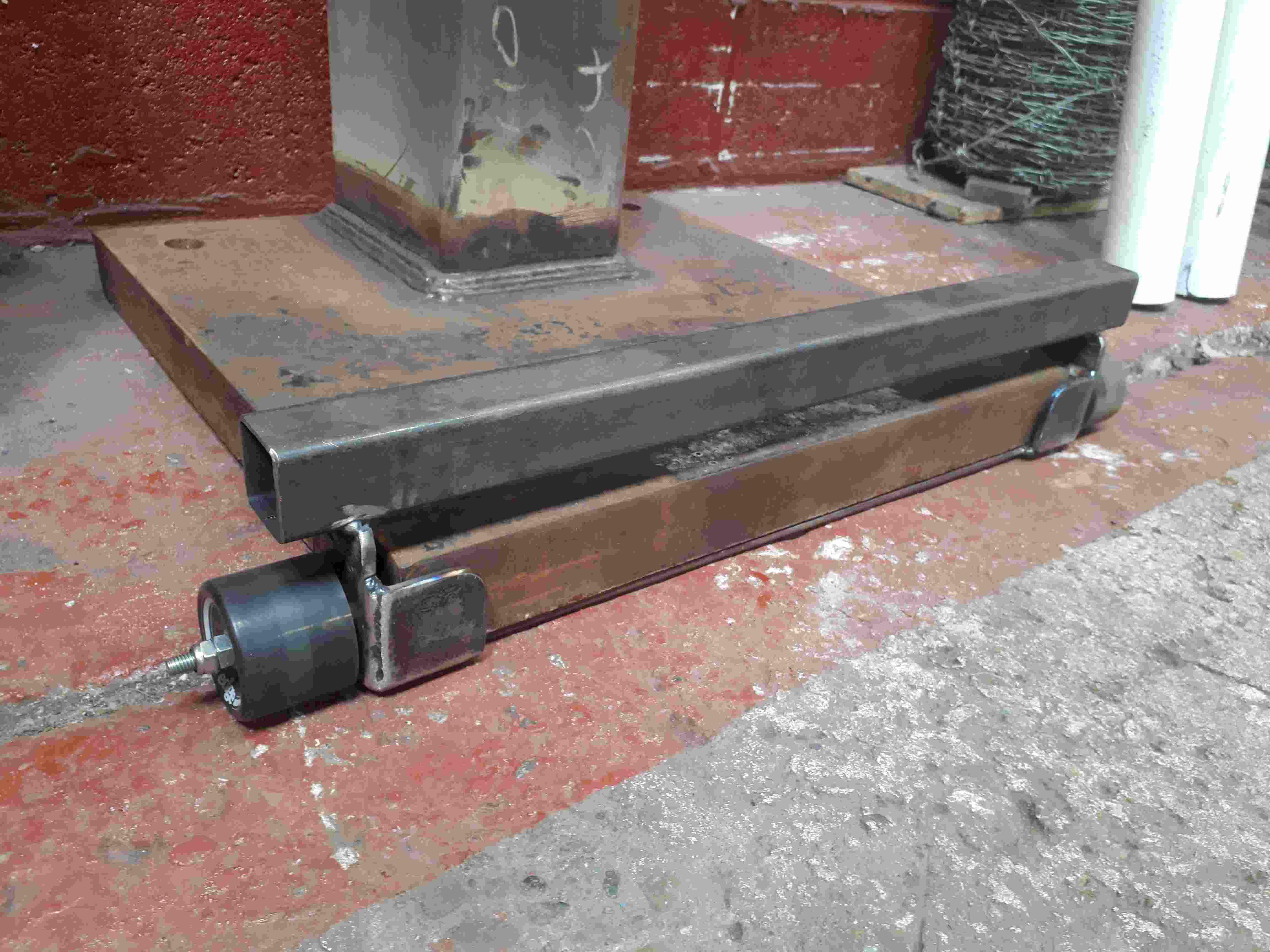
After reading your reply's, I've decided to go with 180bpm which is 3 hits per second. I, also think that much more than this would be a bit scary considering my homemade hammer is as yet untested and its not like I've got experience building them. While I am confident in my fabrication skills, its defiantly wise to be cautious. The diameter of my tyre is 22.5" so, 1360(rpm) ÷ 180(bpm) = 7.55 22.5 ÷ 7.55 = 2.98 So my drive wheel will be 3 inch diameter. Thanks again 4 the help guys. I was in the shop again for 5 hours yesterday, but didn't really make any progress with the build. I did however solve the problem of moving it as i don't have use of a crane or forklift. This is what I came up with and it works a treat It's made from some old skate board wheels and a few bits of off-cut leftover steel. It lifts 1 edge of the base plate up about 5mm and allows you to push the hammer and manipulate it to where u want it. Next weekend I mite get the anvil post put together (Fingers crossed) and actually make some progress. Then it's onto the drive wheel and motor assembly.
-
Thanks chaps 4 the info. My hammer weight will be around 45lb so I was thinking along the lines of 150 bpm. It's all guess work on my part so what do u reckon. Will that be ok?
-
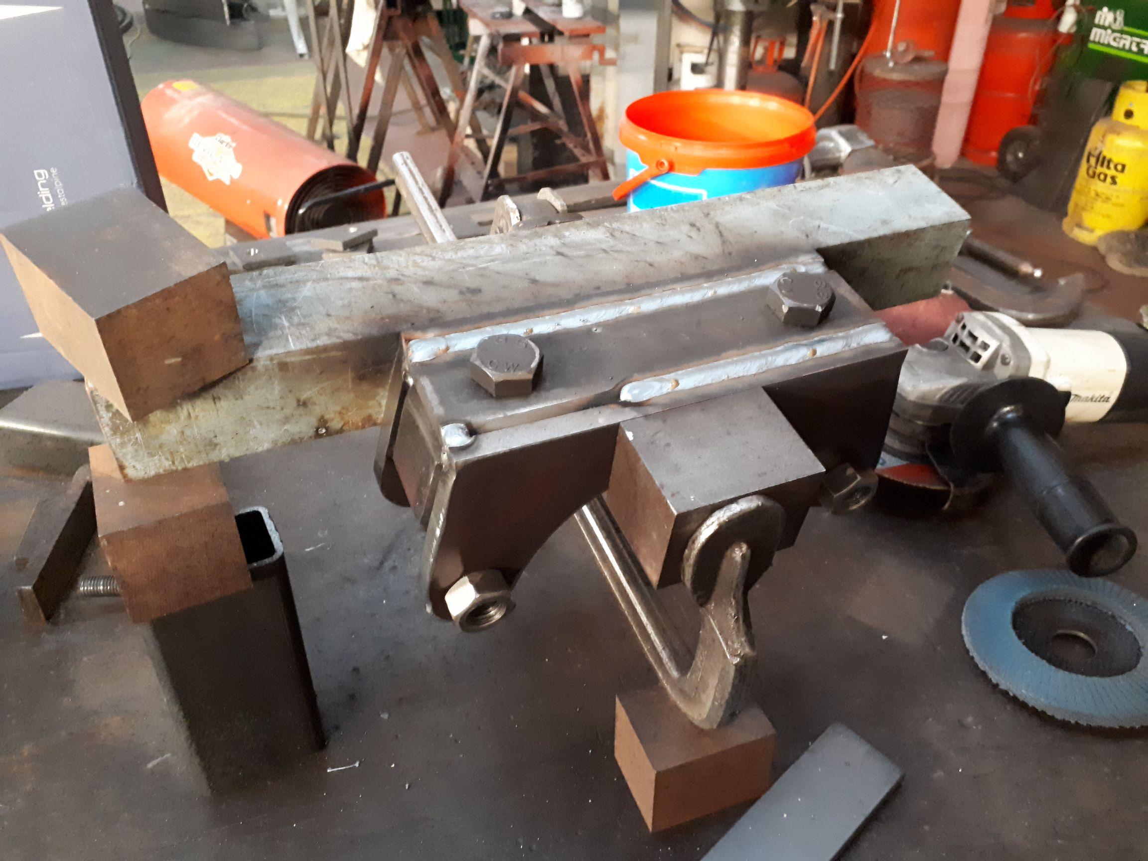
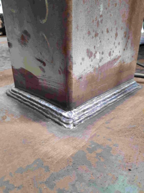
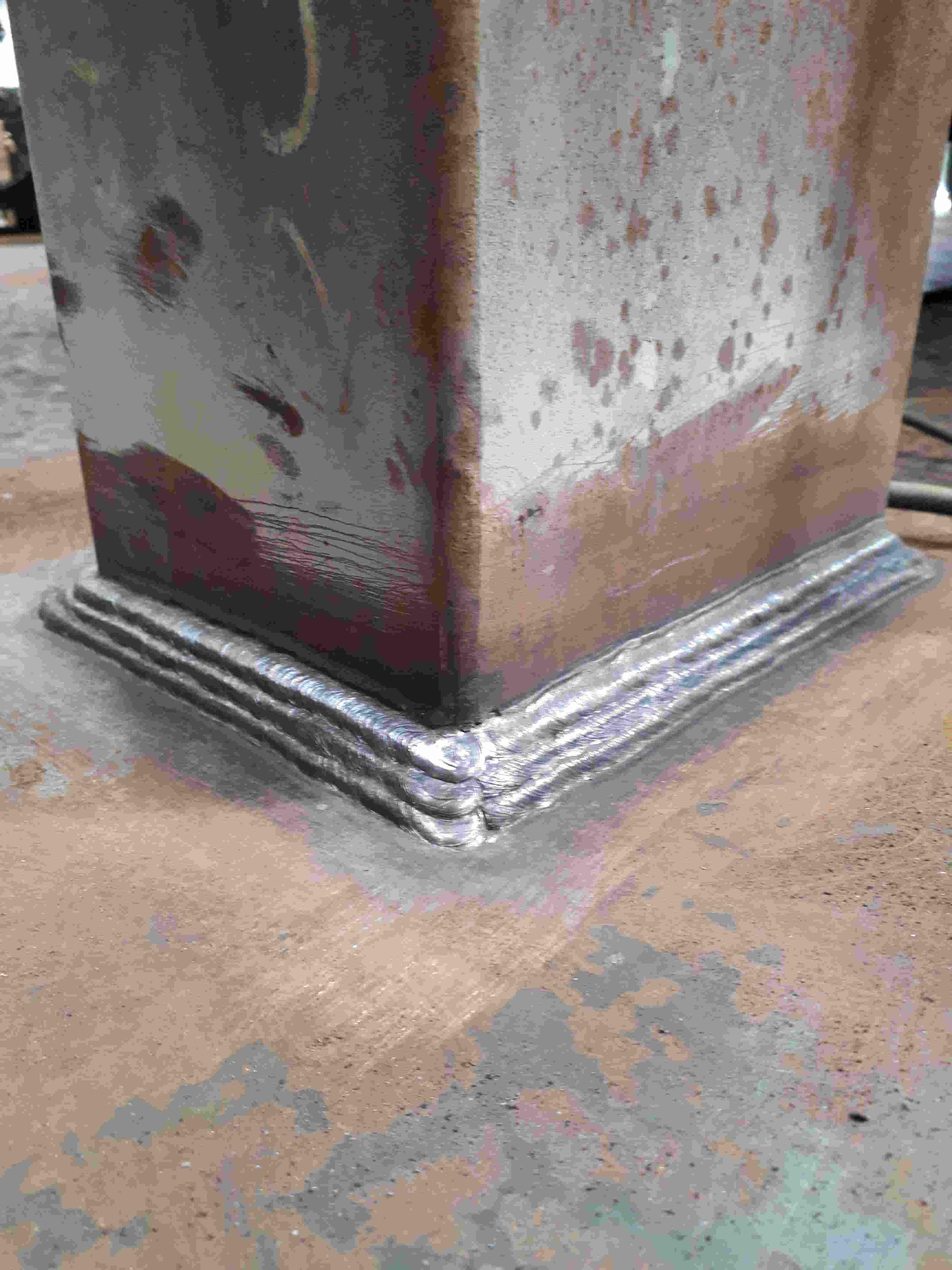
I got another 4 hours graft on my tyre hammer build today and I think it's coming on a treat. I finally got some 4mm welding rods and finished off the welding of the box sec. spine to the 50mm base plt. The result is approximately a 15mm fillet made up of 6 runs. With 3.25's, 1 in and 2 over then with the 4mm's, 3 over those The other thing I did today was drill and tap the 4 M16 holes in the corners of the 50mm, 140×140mm plt, which will then be welded to the top of the anvil post. This is how I'm going to fix the anvil dies or blocks(not sure what they're called)to the anvil post. So that was today's progress I'm getting close to attaching the drive motor so prior to that I need the drive wheel making but are not sure how big it should be? My motor is 2hp and runs at 1360rpm and the wheel is a 15" diameter. If anyone can advise me on this that would be cool. Thanks
-
Self made Treadle-hammer
Gavj75 replied to LeMarechal's topic in Power Hammers, Treadle Hammers, Olivers
Thats an awesome build. Looks like a real pro-job. Nice 1 and I'd also love to see a video of it in use if possible please? -
My First Anvil - Introductions
Gavj75 replied to NoGoodWithUsernames's topic in Anvils, Swage Blocks, and Mandrels
Hi there. I just wanted to tell u that I'm mega-jealous of that anvil u just got. Im certainly not any kind of professional smith so my opinion doesn't really mean anything but it does look like a mighty fine,even sexy, anvil and I reckon it's a great foundation to build up your forging skills from. Gav -
Tire hammer build pics........at last
Gavj75 replied to Gavj75's topic in Power Hammers, Treadle Hammers, Olivers
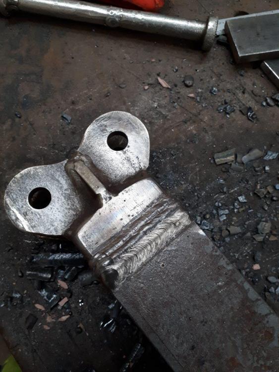
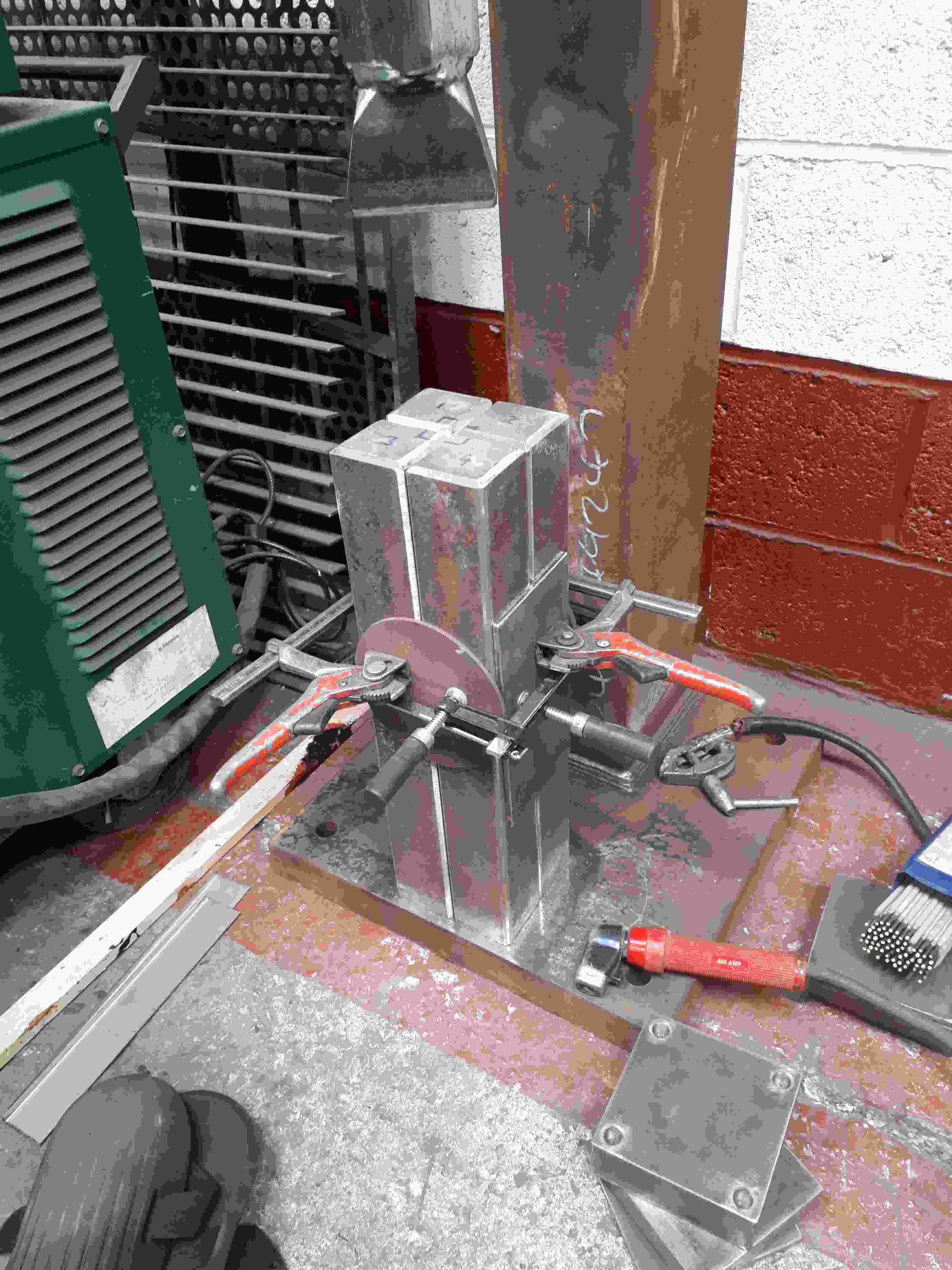
Back in the shop 4 a few hours 2day and soon realised the shaft 4 my hammer is small by about 4inch/100mm. I don't think I took into account how much more movement the flex of the spring gives. So..........today, although busy for 4 hours, my build didn't really progress much. I cut the connection off the top and cut a new piece of 70x70 from the material what will be my anvil post. I replaced that piece with the small hammer shaft I cut off. Hope u can follow that. This results in my post being 100mm smaller and hammer being 100mm longer. I put a large prep all the way round, pre-heated it to remove all the moisture and welded it up with stick Now I had to draw-file all the faces so they were nice and flat and square. Wish I had a surface grinder cos this is the second time doing this and its hard,dirty work when its hot like it was today. After the file I went through the grades of emery paper from 120 to 320 There are still some craters or pock marks in each of the 4 faces but I reckon these will fill with the silicon spray lube I'm going to use and may even help (at least thats what I'm telling myself). I can't take it down anymore anyway because that would create play in its housing which holds it true and plum. So that was my afternoon in the workshop. I'll post more next week when I'll hopefully make some actual progress in my hammer build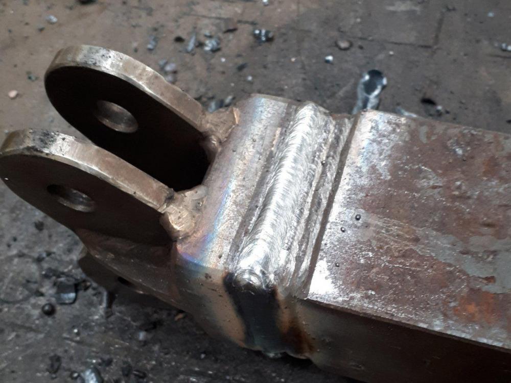
_compress52.thumb.jpg.68c97d573ff43bd21759ca94fecc1e76.jpg)
-
Thanks Jason. Do u have any pics u could post of your build? I just put some more pics up under a new topic heading. " tyre hammer build pics......at last"
-
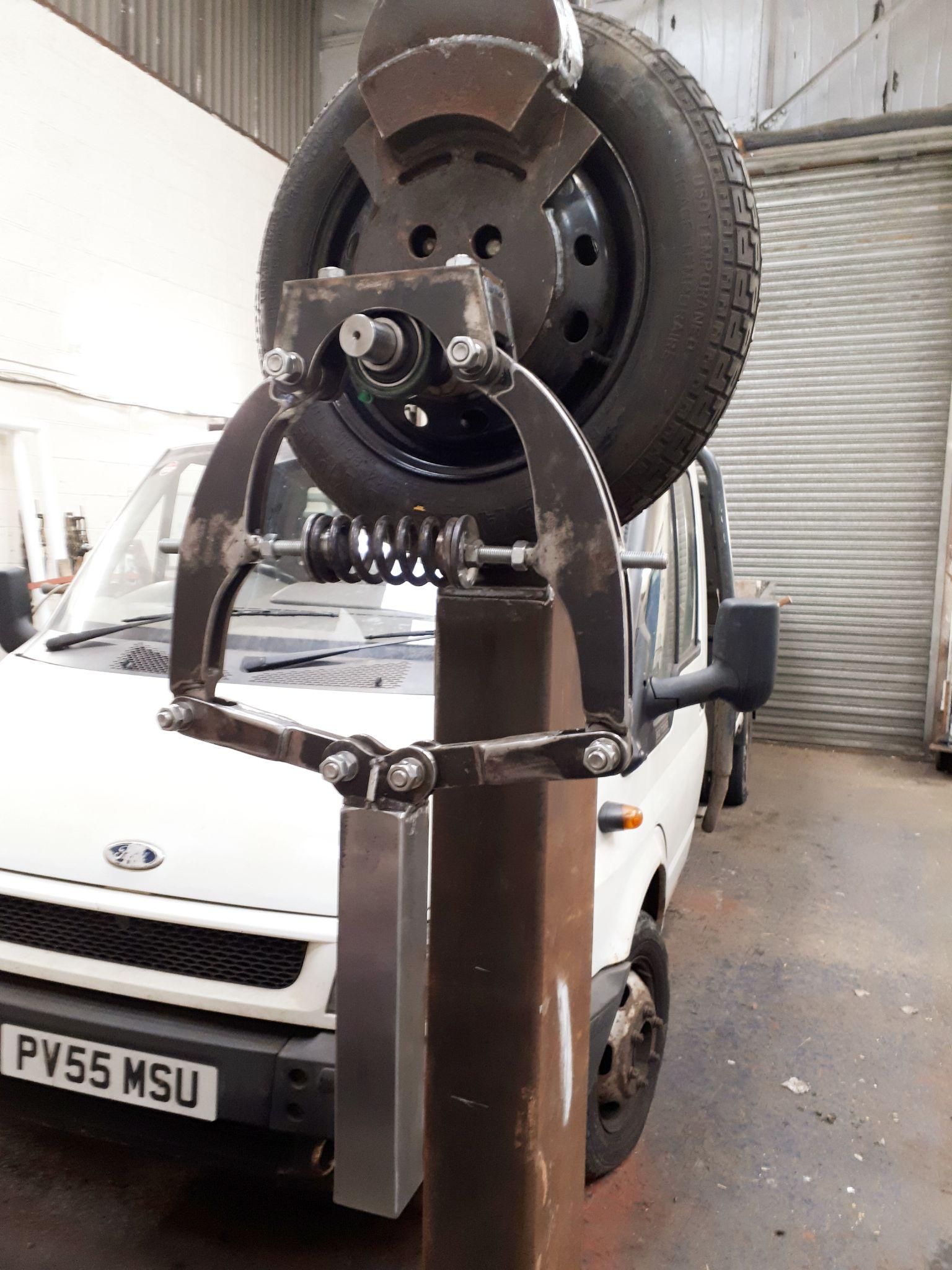
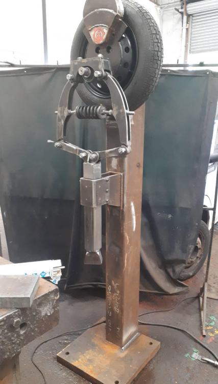
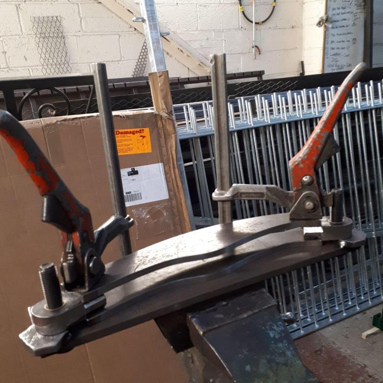
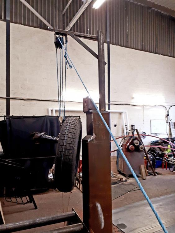
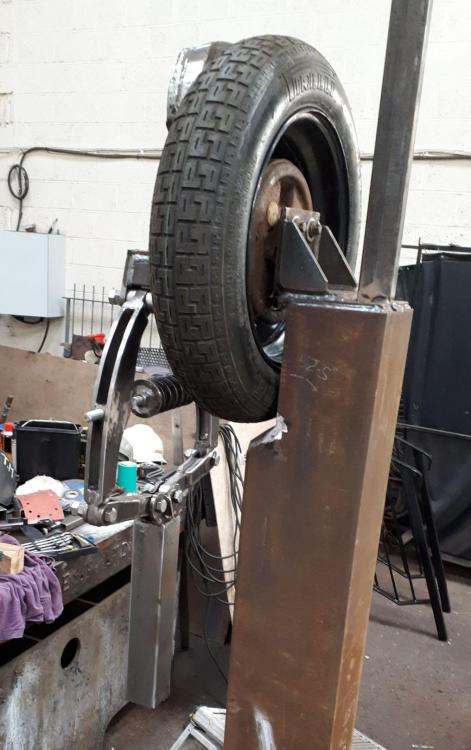
If u have seen my last post u'll know i was having trouble adding photos 2 the forum. Thanks to Chris C, I can now do this. The birth of this project came when a work colleague threw an old 10lb sledge hammer head in the skip at work. Naturally, I dove straight in and salvaged it. I wasn't sure what for at this point but knew it was worth keeping. I had a 1500rpm, 2h/p motor which the mechanical fitter at work gave me when I was building my beltsander. I didn't use it as i'd just got a 3000rpm, 2h/p motor from a kind chap I met on the forum. Thats when the idea to build a tyre hammer came to me but I still needed somewhere to build and house it. A friend has his own small workshop and he agreed that I could do it there. And that was that. I work as a Plater so was able to get hold of most of the other materials through my job. 150 × 200 × 10thk box sec. 4 the "spine". 500 × 500 ×50thk base plate and 70 × 70 solid square bar to make the anvil post( 4 together, 140x140) and main hammer shaft from. Anyway, they say a picture speaks a thousand words so have a look: Not sure whether I'm using the sledgehammer head or forklift tyne instead??? Don't u hate it when your mig wire runs out in the middle of your weld made a jig to assemble the 2 spring arms to make sure the centre's are both the same on them had to build a pulley system as i couldn't lift the tyre high enough and put a bolt in to hold it. Because of COVID 19 I had to do it on my own. My friend was watching me do this but couldn't help. It was tough. starting to look like a hammer my design to keep the hammer straight and true. 120 × 50 × 6thk brass on all sides with minimal clearance. I'll use silicone grease to lube it. Hope it works ok but I guess we'll see in time. Fingers crossed . I'll add some more pics as the build progresses, in the meantime if u have any questions I'll do my best to answer them. Thanks Gav


_compress52.jpg.5dc8a83ffee3b351e5874e2c2b133242.jpg)