Trevor84
-
Posts
168 -
Joined
-
Last visited
Content Type
Profiles
Forums
Articles
Gallery
Downloads
Events
Everything posted by Trevor84
-
The burners in this last forge arr different burners all together, they are designed as 3/4" burners and arr still in testing as well.
-
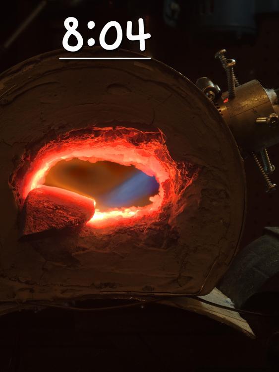
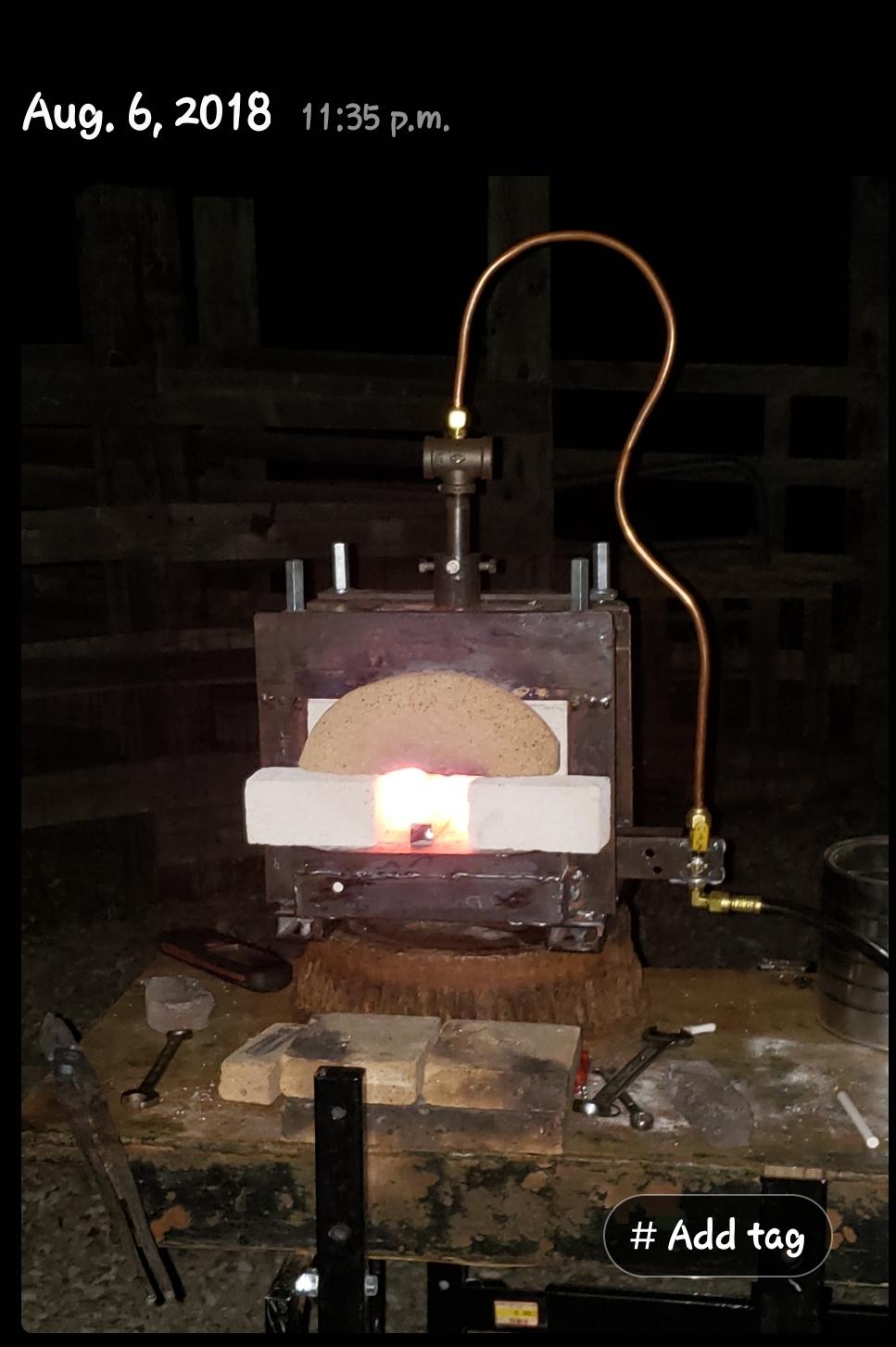
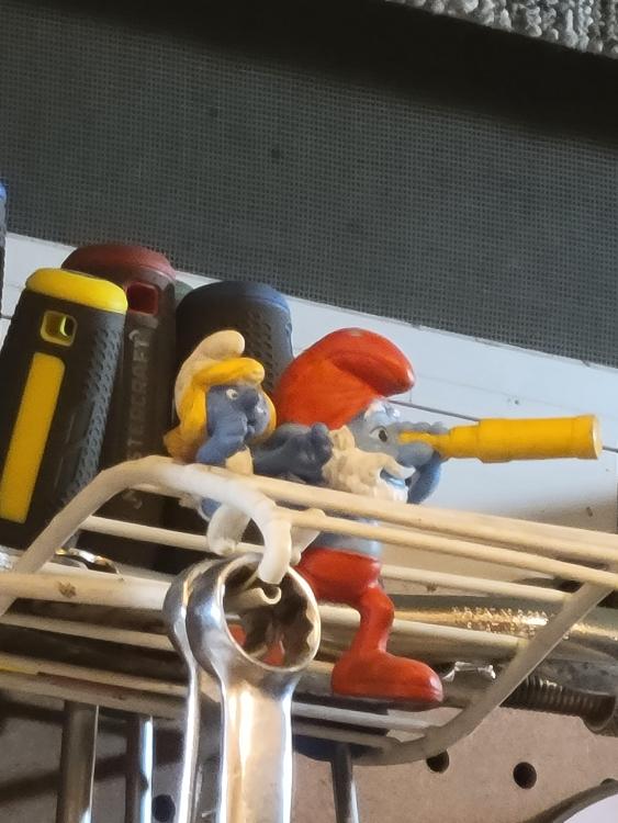
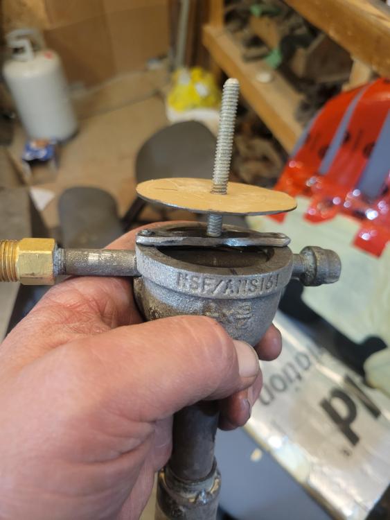
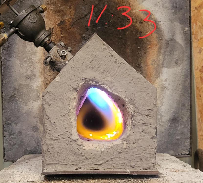
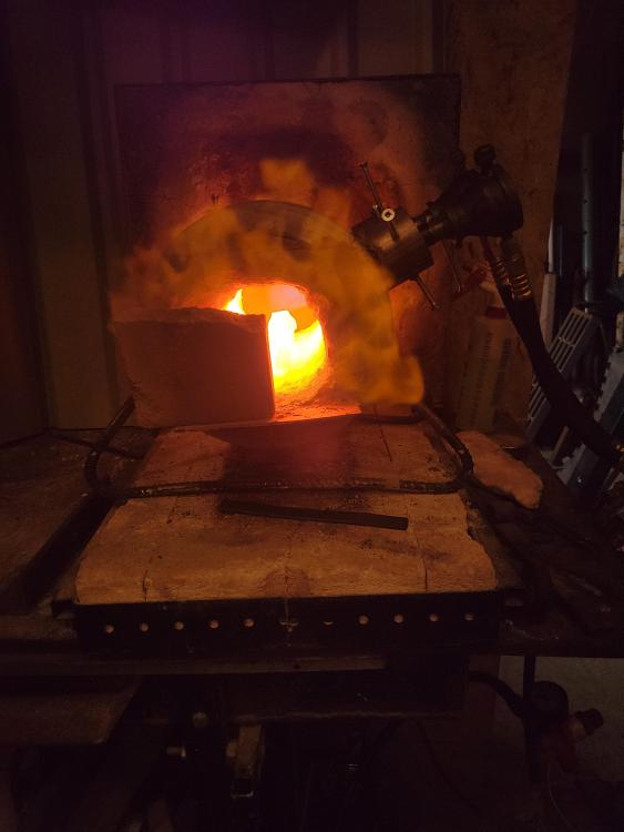
Robert geez 8yrs so young, I'm sorry for you loss Mike, you are so right they do love summer! I may be missing something in my description or I labeled the diagram incorrectly I'm thinking...... There is no lamp rod, the threaded rod at the top of the sketch is jut there to hold the choke plate, what I am calling the fuel rail is still the classic 1/8" nipple that mounts in the opening of the intake horizontally. Made sure they were dead straight then tac welded in place after using jbweld to seal the mig contact tip in place. So downside the fuel delivery is locked in place, upside the fuel deliver is locked..... The only thing I can adjust is the depth of the bushing "throat". I am happy with the alignment of the jets in these two but if the 0.8mm flows too much fuel for the half inch pipes I'm kind of limited on options for adjustments. If I swap out the half inch nipple / bushing for a 6"x3/4" it should mix a bit better and reduce that dragon breathe. (the last pic that is really nice is a burner like these but using the. 0.023.... The pic of the forge with heavy dragon breathe is using burners that have the 0.8mm tip) If it seems like I am jumping burner to burner it is because I have a couple on the go, I have a couple made with the 0.023 and a couple with the 0.8mm tips (kind of screw up's). I also have two more micro burners on the go etc..... Jery, what you say about the choke is one of those tid bits I really utilize! With choke: build for lean and speed and choke to get neutral No choke...... Build it right and tune it to the forge. (kind of thing) I'm hoping to get to the shop in a few days and will try out a few things like plunk the 0.8mm burners into my larger "300CI minion forge" and try the micro burners in 150ci forge above. Oh geez Thomas at least your preciois was with ones that loved her and not a stranger. Oh man I feel bad for the other guy they just don't understand...... Maybe this shows how the choke plate and fuel rail are mounted in these burners Here's the minion forge, well the beginning of one. I need to embellish around the eyes, maybe make them look like binoculars.

-
Sitting here re reading your comment about orifices Mikey and looking at my pictures and drinking coffee and making sure the cat doesn't start running or going upstairs.... Anyway the last two burners I made I used the 0.8mm contact tips like in these picture's above, I tried tge two together inside that forge that was belching fire. There was too much air and fuel for the chamber so I ran with one of the burners. I start this thread, write out instructions, post pictures and seen the original burners with the great flames used the 0.023 tips so I deleted those photos and continued posting pics. Not clueing into the mix up I just made I respond to Mike to confirm the size of the hole in the contact tip...... It doesn't matter whether I measured an accurate 0.8mm and it was actually 0.8mm or 0.85mm both are way too big for a half inch mixing tube (insert face palm) The 0.025 torch tip cleaner will slip into the 0.023 contact tip smoothly without much wiggle at all. Soooo I'll turn these burner heads into simple "3/4" burners" and ditch the fancy reducer bushing. I'm getting decent at drilling straight through the rim of the bell reducer so I'll whip up a couple more with the 0.023 contact tips again. So I get these beauties again. Yes of course my fuel rail (the 1/8" nipple is welded in place and the contact tip seals with jb weld ;-) (oh and the Charlie cat is 16 years old and I can barely keep up to him, he is recovering from a compressed nerve from sitting weird all doped up at the vet. His front leg had no feeling or control so when he'd walk the foot would roll in and he'd collapse on the top of the foot, it looked like a shattered ankle at first..... oOps sorry wrong page for that but geez my heart was going to blow if I didn't tell someone it's been a long couple days watching him recover, I'd rather stick my hand in the forge than watch that again)

-
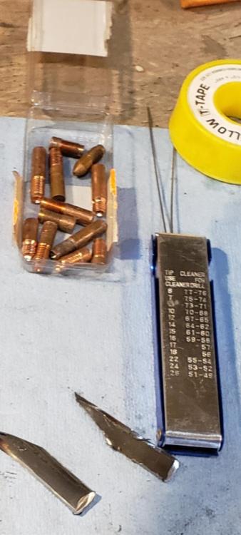
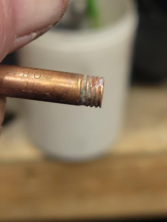
I've got a few different brands of contact tips some quite different I size others seem to be quite close to the advertised size at least according to the torch tip cleaners. I have used the torch tip cleaners closest by the thousands and end up with 0.025, 0.031, 0.035. Now I could be wrong because I'm using $30 digital vernier calipers but I figure if the caliper says the tip cleaners a certain size and I can't get the next size up into the hole ie the torch tip cleaner that I've measured at 0.030 won't fit in the 0.023 contact tip. Ughh it sounds like I'm arguing I think..... I'm only sharing observations.... The 0.8mm and the 0.023 contact tips were el'cheepos so for me they're great that they're accurate on the flip side they'd probably jam like crazy at the slightest build up when used for welding Is there a better way to verify the actual orifice diameter? Again I used the vernier to confirm the thickness of the torch tip cleaner then tried sliding the cleaner into the contact tips using a drilling motion and calling its diameter whatever the largest tip cleaner fit. (clear as mud right)
-
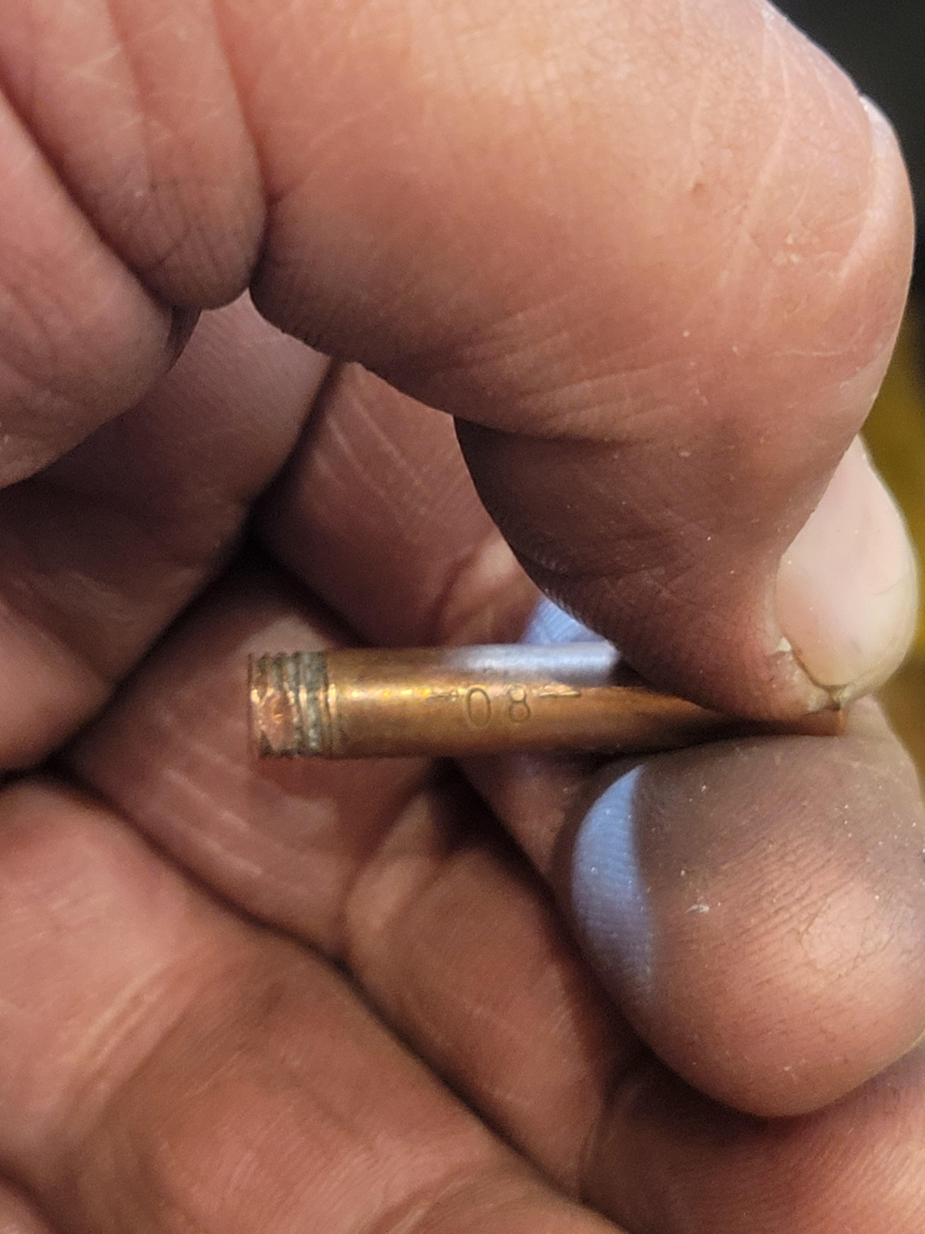
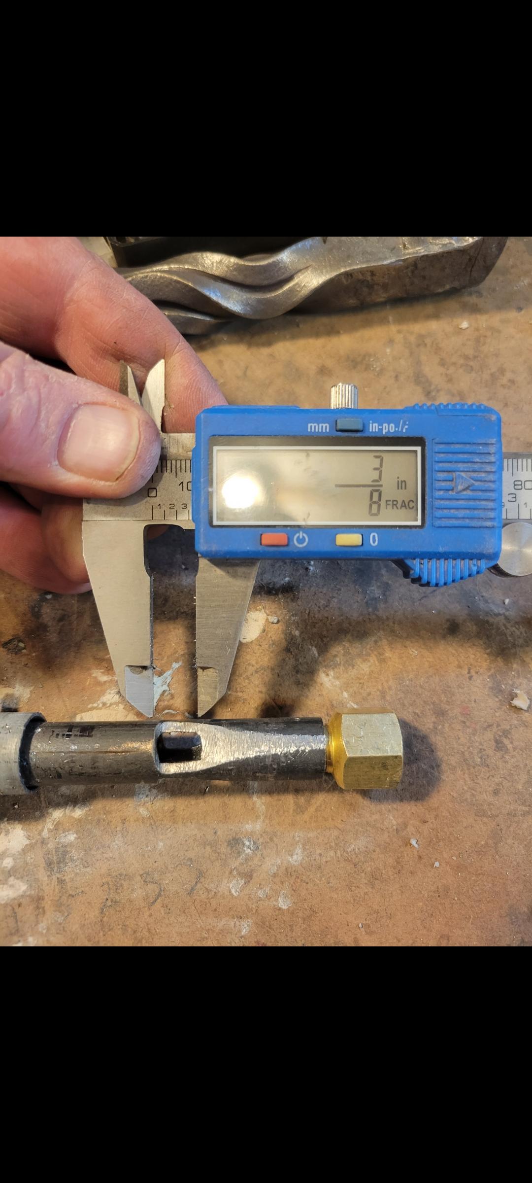
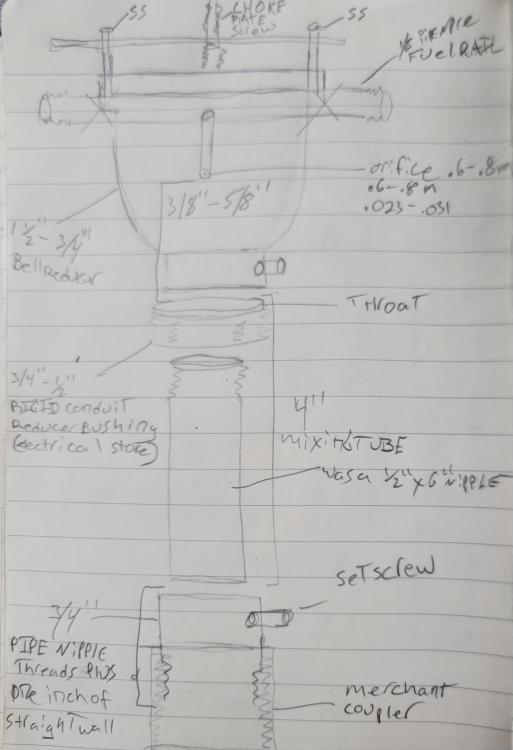
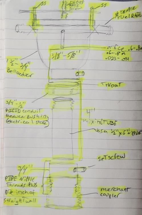
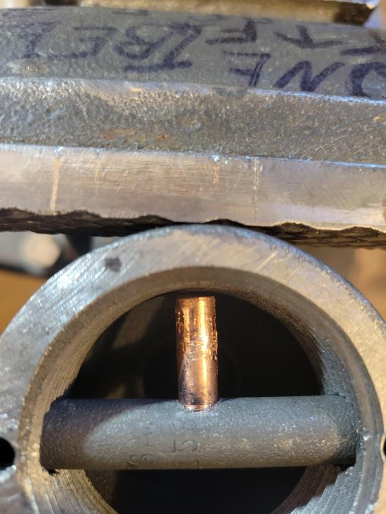
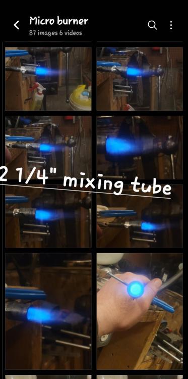
I doubt you'll be able to read this but maybe maybe you can...
-
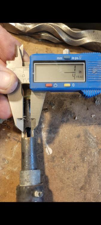
Maybe an easier way to say it would be: Screw the 1/2"x6" pipe nipple into the rigid conduit reducer bushing, then measure from the end/top of the bushing down 4" and cut off nice and smooth. The bushing and the pipe nipple together should be consider "mixing tube". So if you separate the two your pipe nipple will be less than 4" by a scooch. The top side of the bushing is the throat.... The measurement from the tip of the contact tip to the throat on mine is 1/2". Oh another addition.... At the base of the bell reducer I drilled and tapped for a set screw, now you can adjust the mixing tube/throat up and down about 3/8"-1/2"and tighten the screw against the outside of the bushing. I'm going to try and sketch something up because I'm kurfufelingmy my thoughts.
-
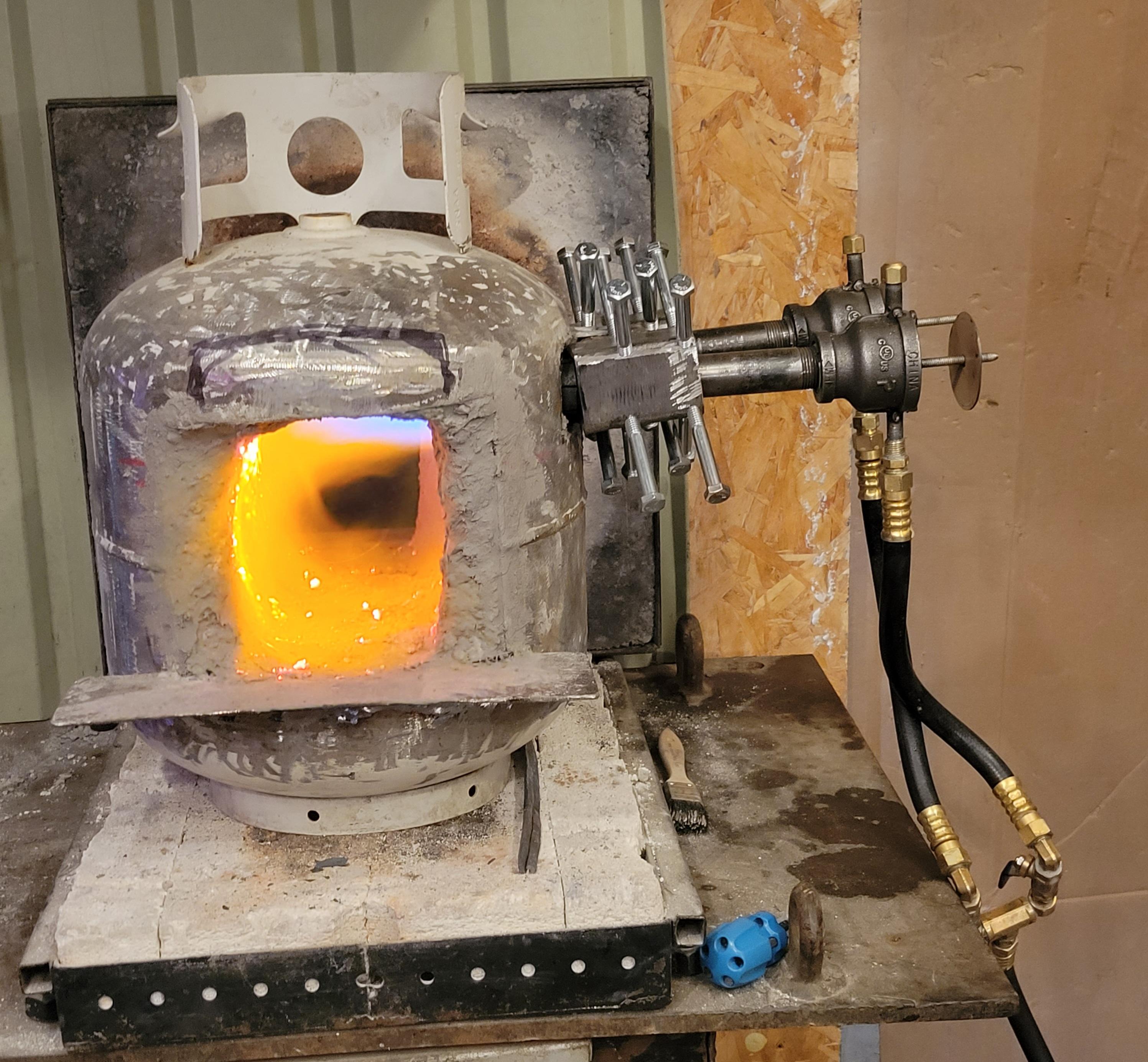
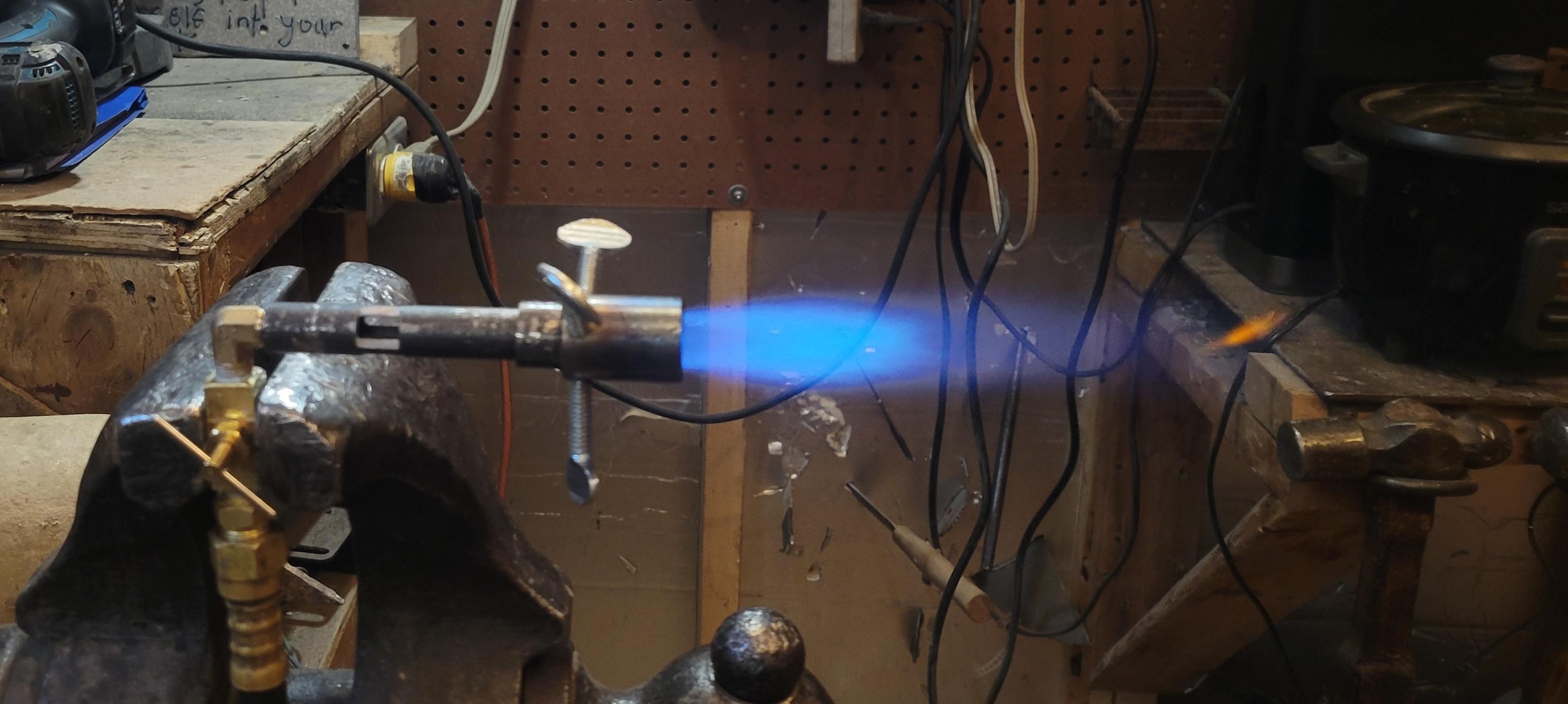
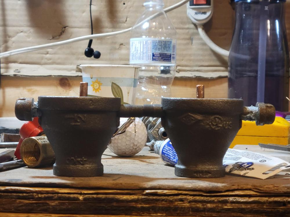
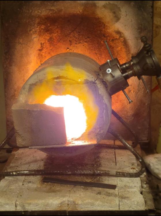
The last pic is with the two 1/2" burner's and there is just too much flame with two of these especially with the 0.8mm instead of the 0.023 I had in originaly. I may go back to the 0.023 depending on the forge they are going into. This double burner forge will be getting two of my micro burners hopefully in the next week here. The school house forge has the 0.023 (0.6mm) orifice .
-
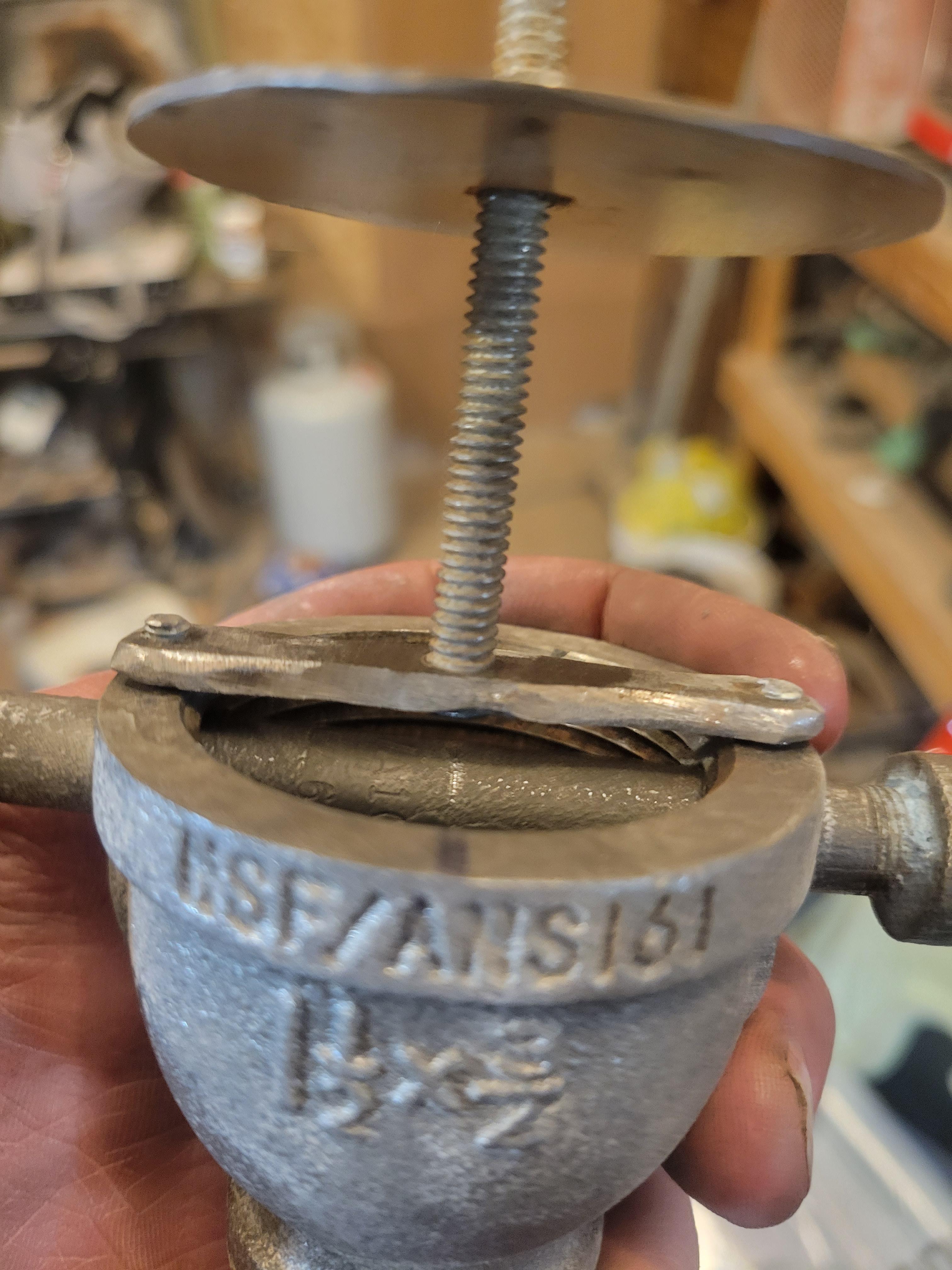
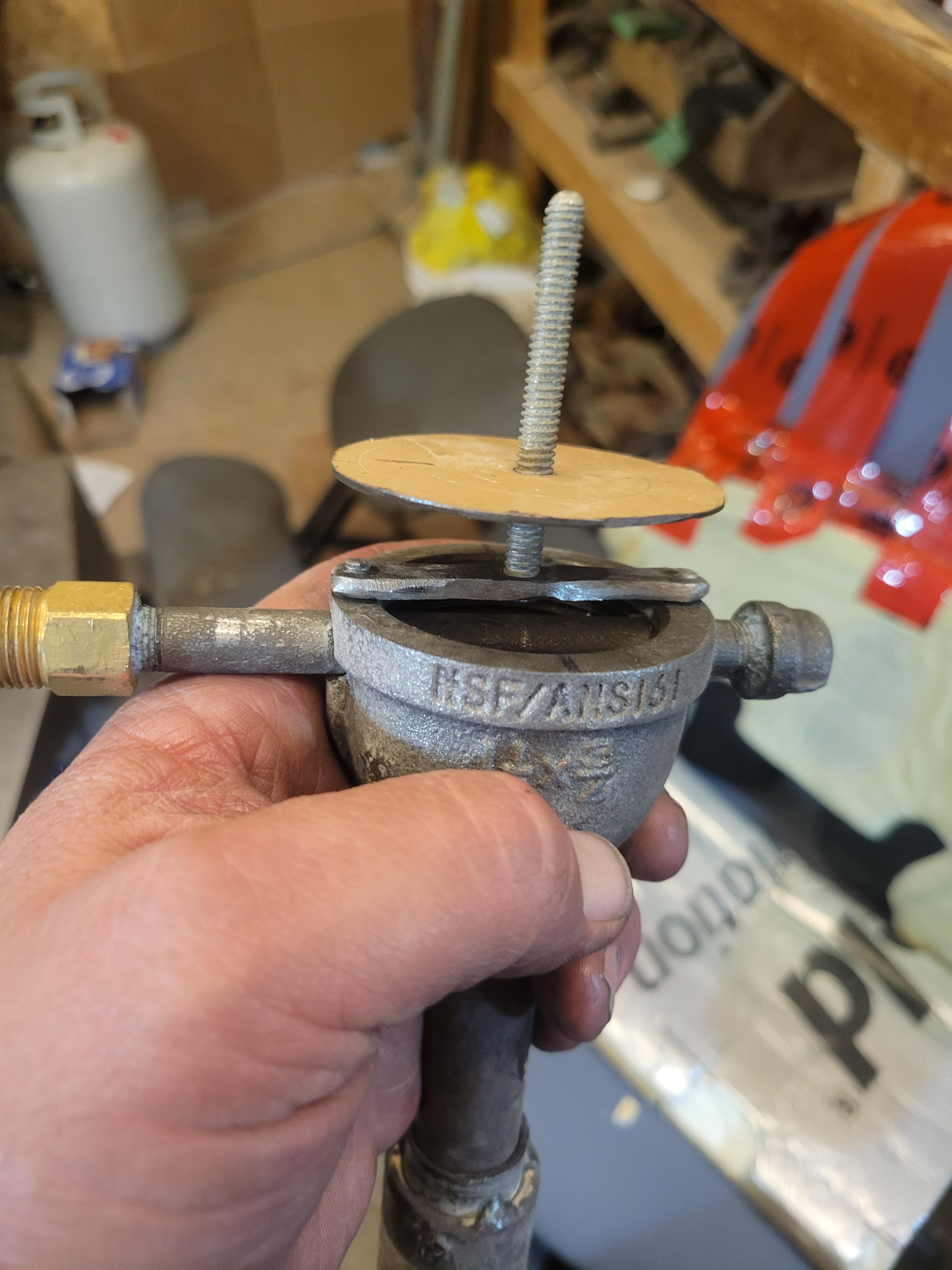
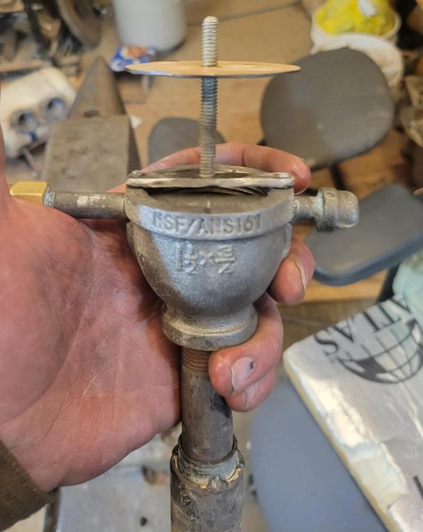
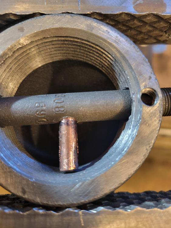
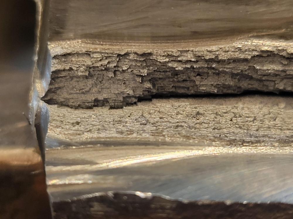
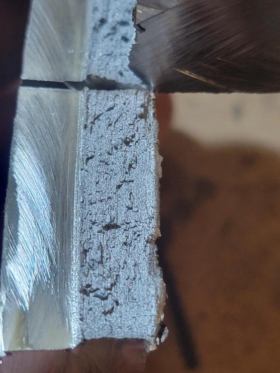
This is the conduit reducer bushing, note the rolled edge where the throat would be. The tip of the contact tip is 1/2" from the initial rolled edge of the bushing, so 1/2" from orifice to throat/narrowest part. This is with on 1/2 " burner


-
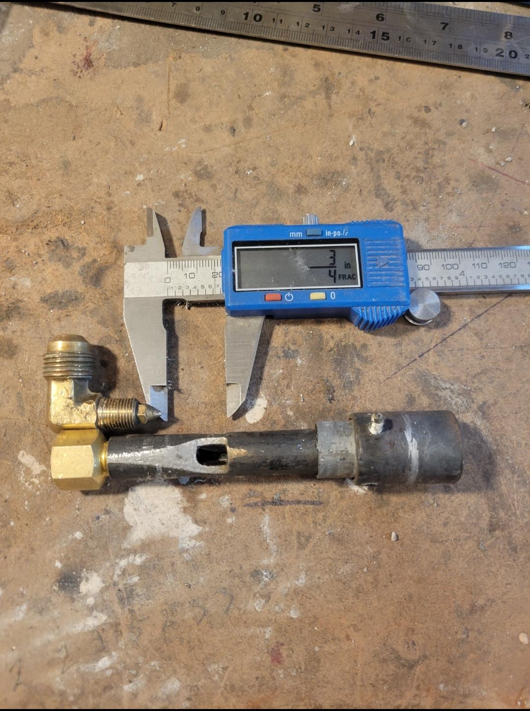
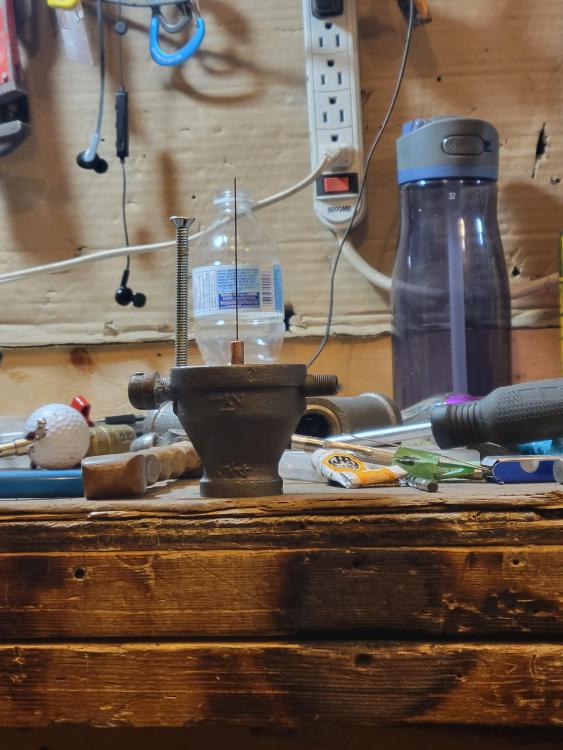
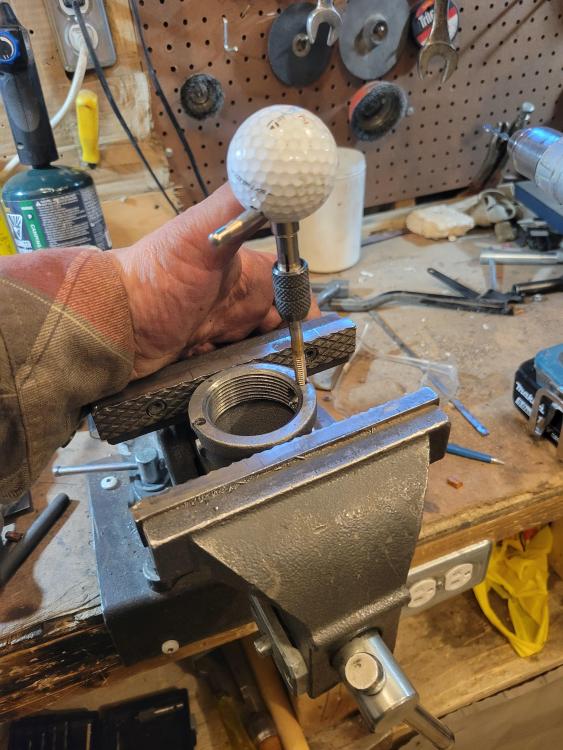
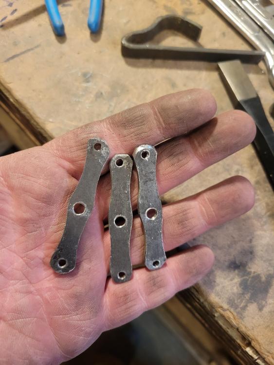
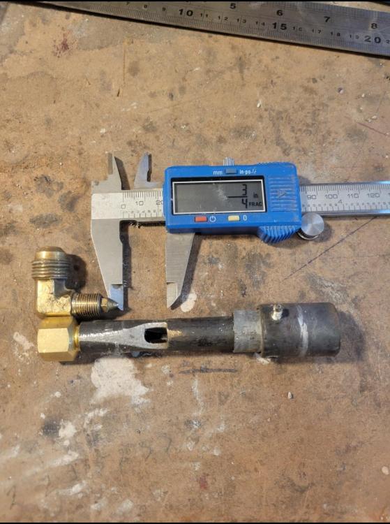
Here's my latest twist on Ron's classic EZ burner..... 1/8"x 4" sch 80 pipe nipple 0.8mm mig contact tip 1/8" pipe cap 1 1/2" - 3/4" bell reducer 3/4" - 1/2" "rigid conduit reducer bushing" 1/2" X 6" (measure 4" including 1 threaded end and discard the rest The nozzle is a piece of 3/4" tac welded to a 3/4" merchant coupler ie straight thread with a little set screw I run my 1/8" nipple/fuel rail through bell centered at the bottom of the exterior lip with a set screw on either side to secure the fuel rail. I drill and tap the fuel rail to take the mig tip. I trim some threads off the mig tip and then trim enough off the tip so you can just spin it around inside the opening. The graphite refill is a 0.7mm so if you bump it one way than the other you can zero in on straight, I don't have water in my shop to do the water jet test but this seems to get me close. One you've confirmed your jet is straight, centered, sealed etc then hit it with a tac weld or just rely on the set screw. A choke plate can be added by drilling and tapping a strip of 3/8" flat bar, utilize the set screws and holes to secure the flat bar then turn down the center bolt and it'll lock against the fuel rail and help secure it if you didn't tac weld it. Pictures lots of pictures coming really soon.
-
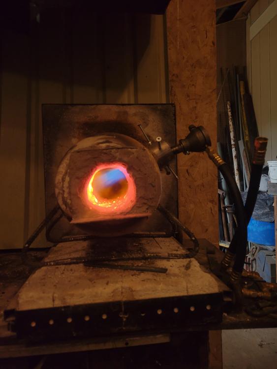
87 ci..... Well than the double burner I have there should be primo, I think it's about 150ci or aprx 75 ci per burner. When it comes to swimming in the pool..... I have definitely been doing laps in pools like burners/forges 101 so when I dive in at the shallows I manage to slip into the water between the surface and the floor without smashing my face..... It's almost been 4 years since my first build which had come after almost a year of studying up. This is a simple 8 soft brick forge running a 1/2" Frosty T, I hadn't seen any 1/2" versions so I even had to message Jerry to confirm a dimension or two iirc, I still have the burner head on my bench.
-
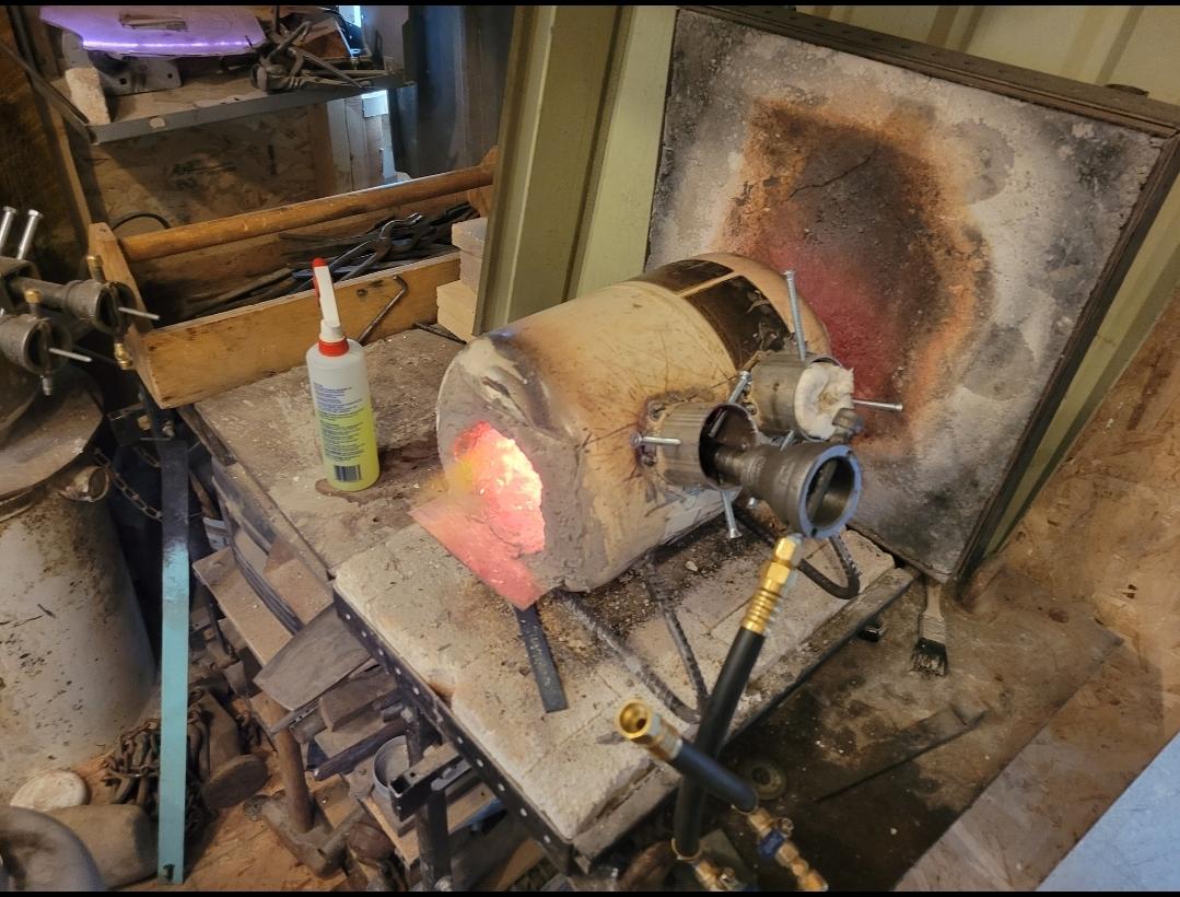
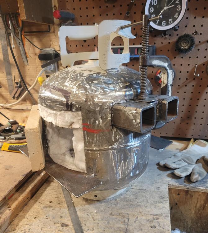
Mikey suggested two if these burners may run a frean forge so I'm gonna try a pair in this 15# tank, interior is 4"D 12" long. I tried two of my modified half inch EZ burners and there was just too my h flame for the space so I ended up running the forge with a single half inch burner angled towards the rear of the forge. I'm starting to think my new half inch burners pack the punch of my older 3/4" burners and possibly the 1/4" may replace my old half inch. I haven't ran enough gas through these forges to make any solid/reliable observations regarding efficiency, max temp and that stuff. (Does it really matter if the tank of fuel lasts 1.5hours longer? Not to me really, especially since with my body it's race against time as soon as I stand up to when I have to call it a day. So the faster and hotter I can run the better, saving money is good but if it will take me a year to realize then meh it don't matter much.)


-
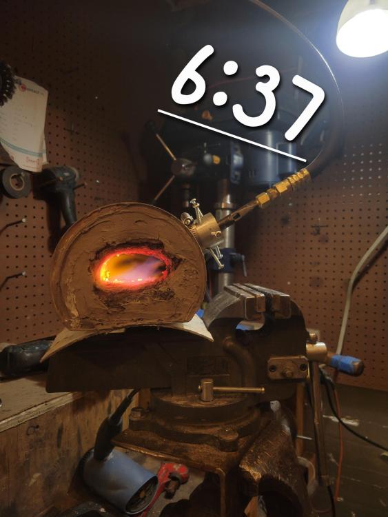
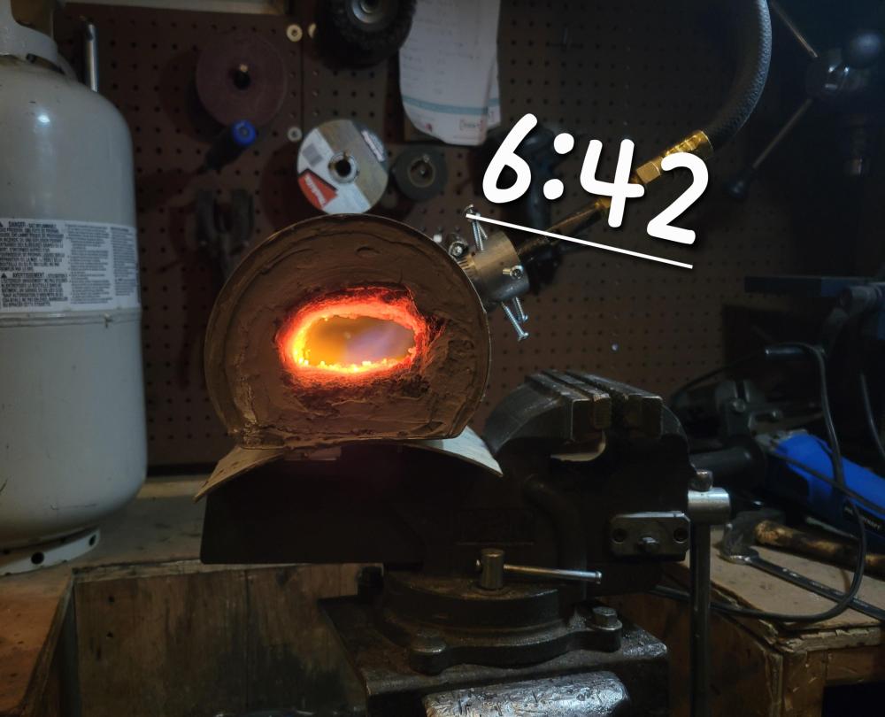
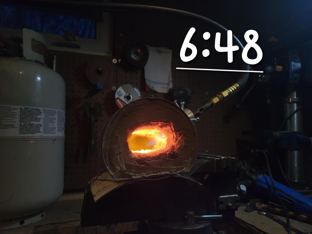
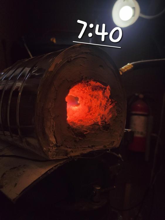
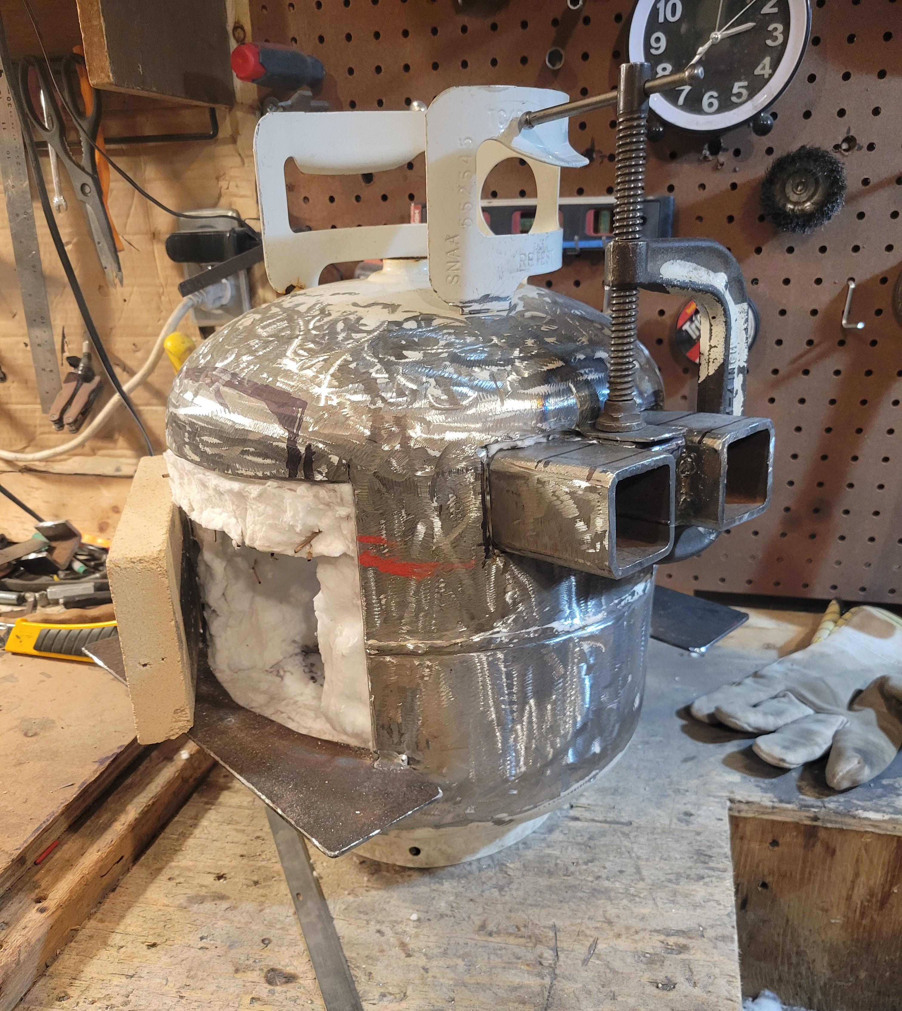
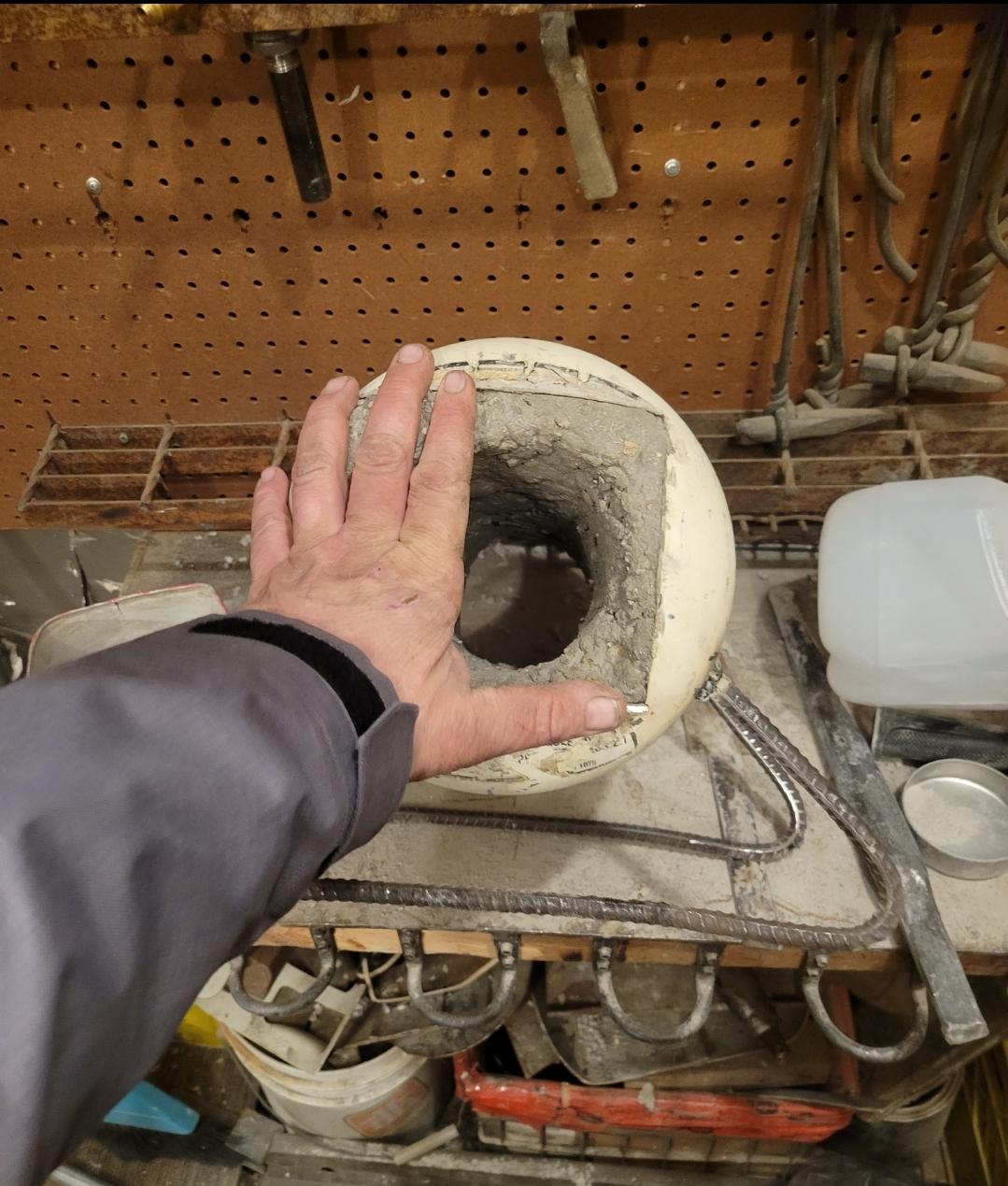
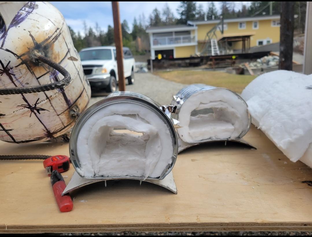
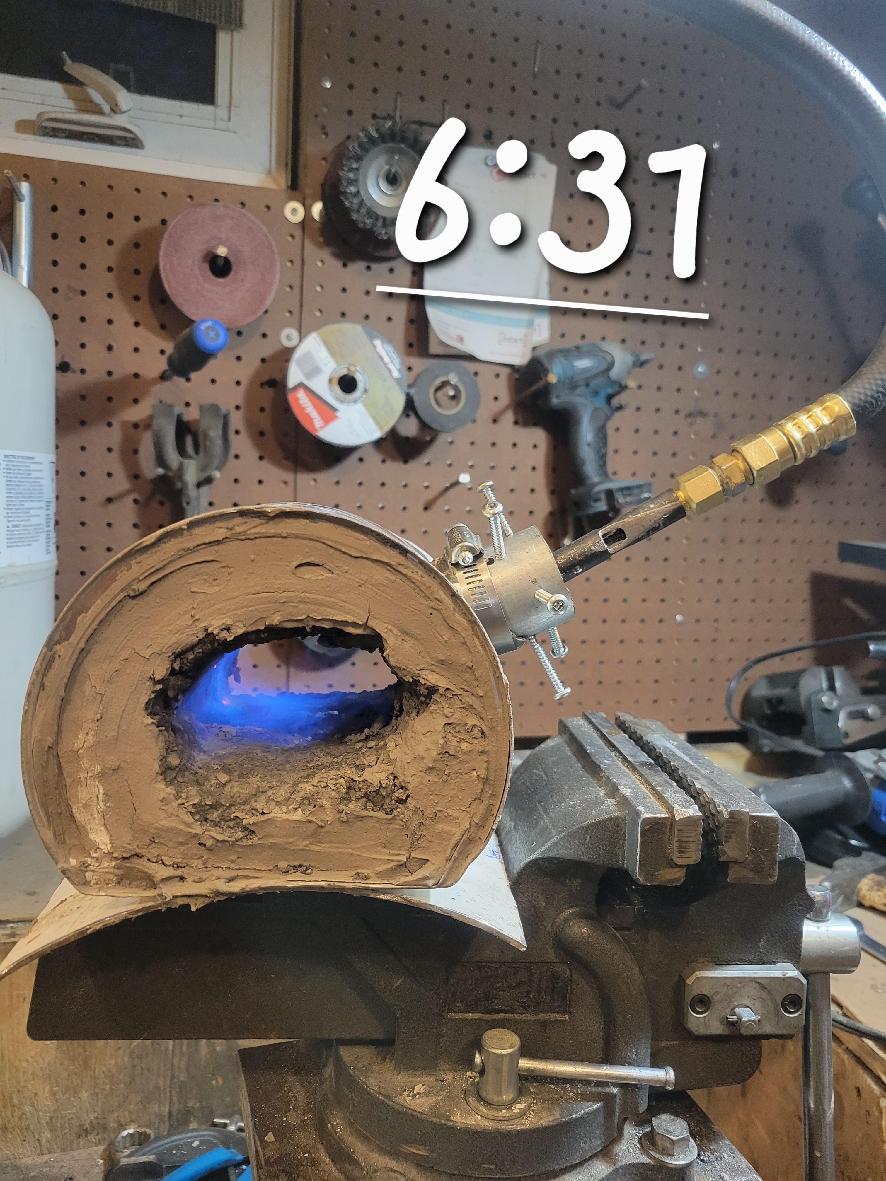
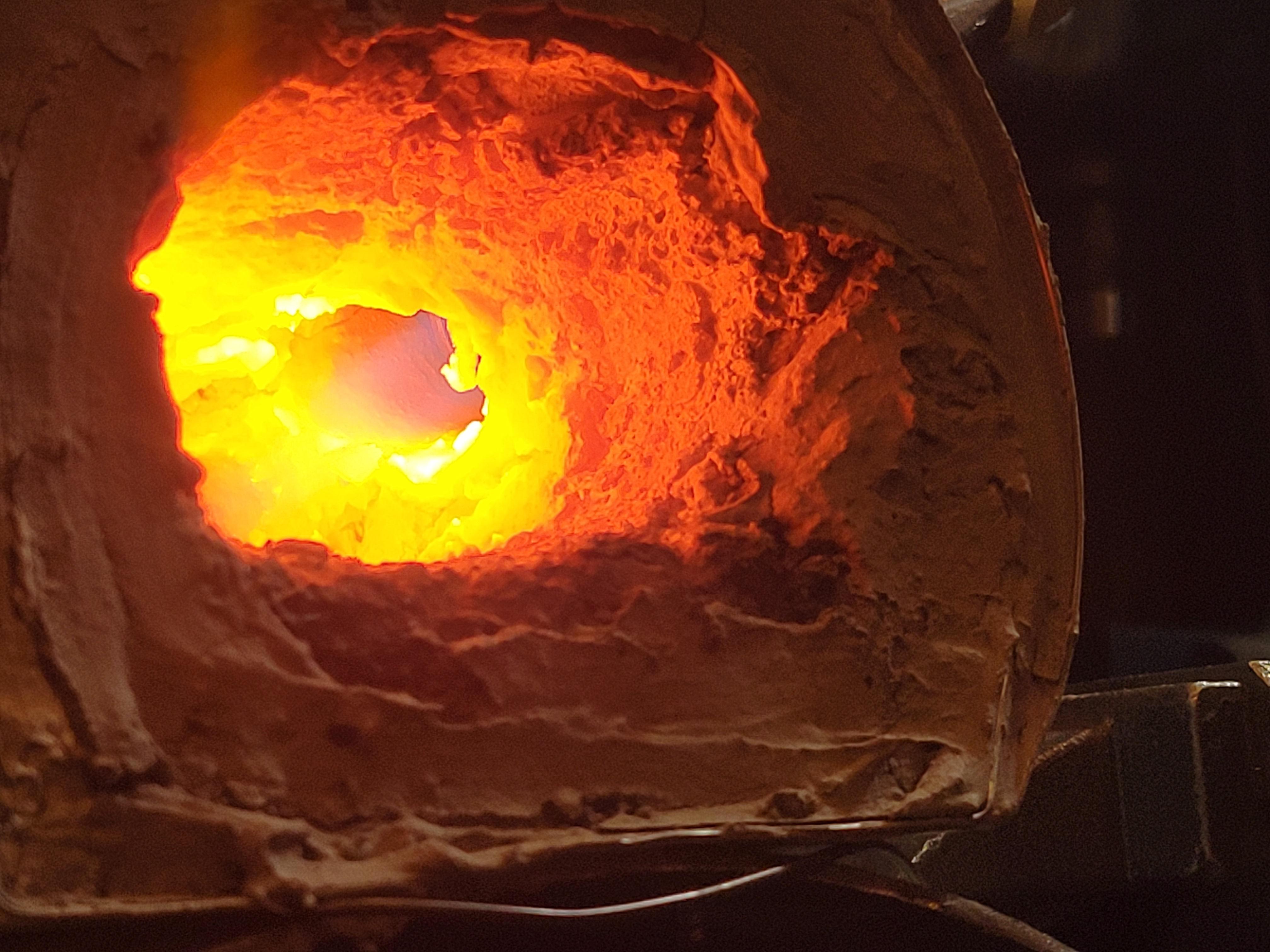
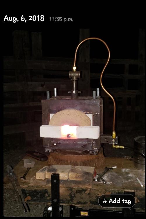
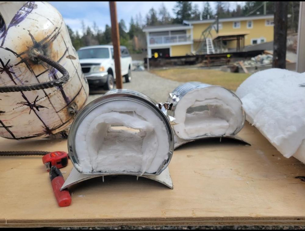
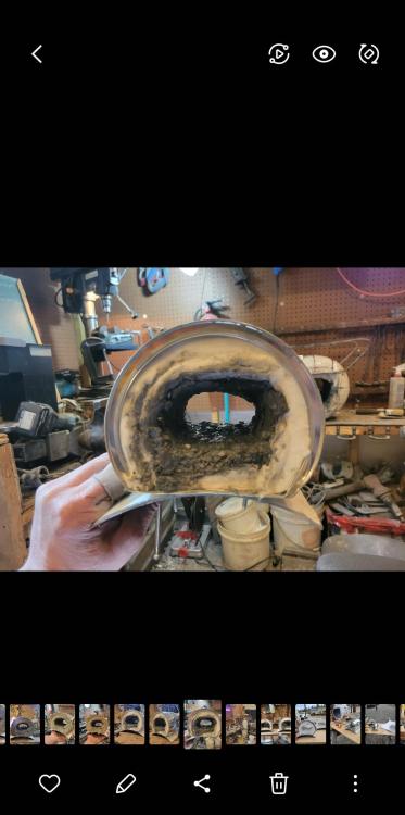
Yes thank you I agree ... I hear you loud and clear, the goal waaaaas to get an air foil shape to the inner chamber and the burners flame was meant to run along the ceiling so you could lay small knife blank shapes on the floor with no direct flame. The insulation shown is not the end result it was mid conception. Eventually I did a combo of 1-1.5 inch but padded the upper section where the flame hits closer to 2 inch thivk kinda sorta. The castable is maybe 3/8" thick so ya I probably looking at 40 - 50 cubic inch ID. The way I have the burner mounting tubes welded to the base not the forge makes it easy to readjust and level that burner out so it slides along the ceiling instead of helitting the corner like you say
-
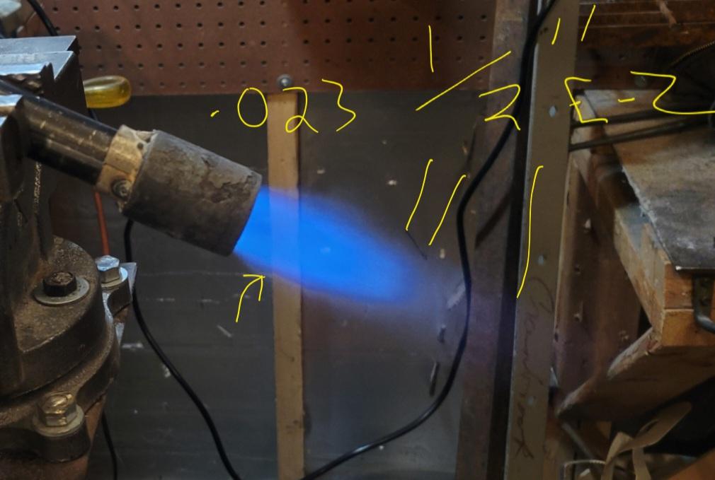
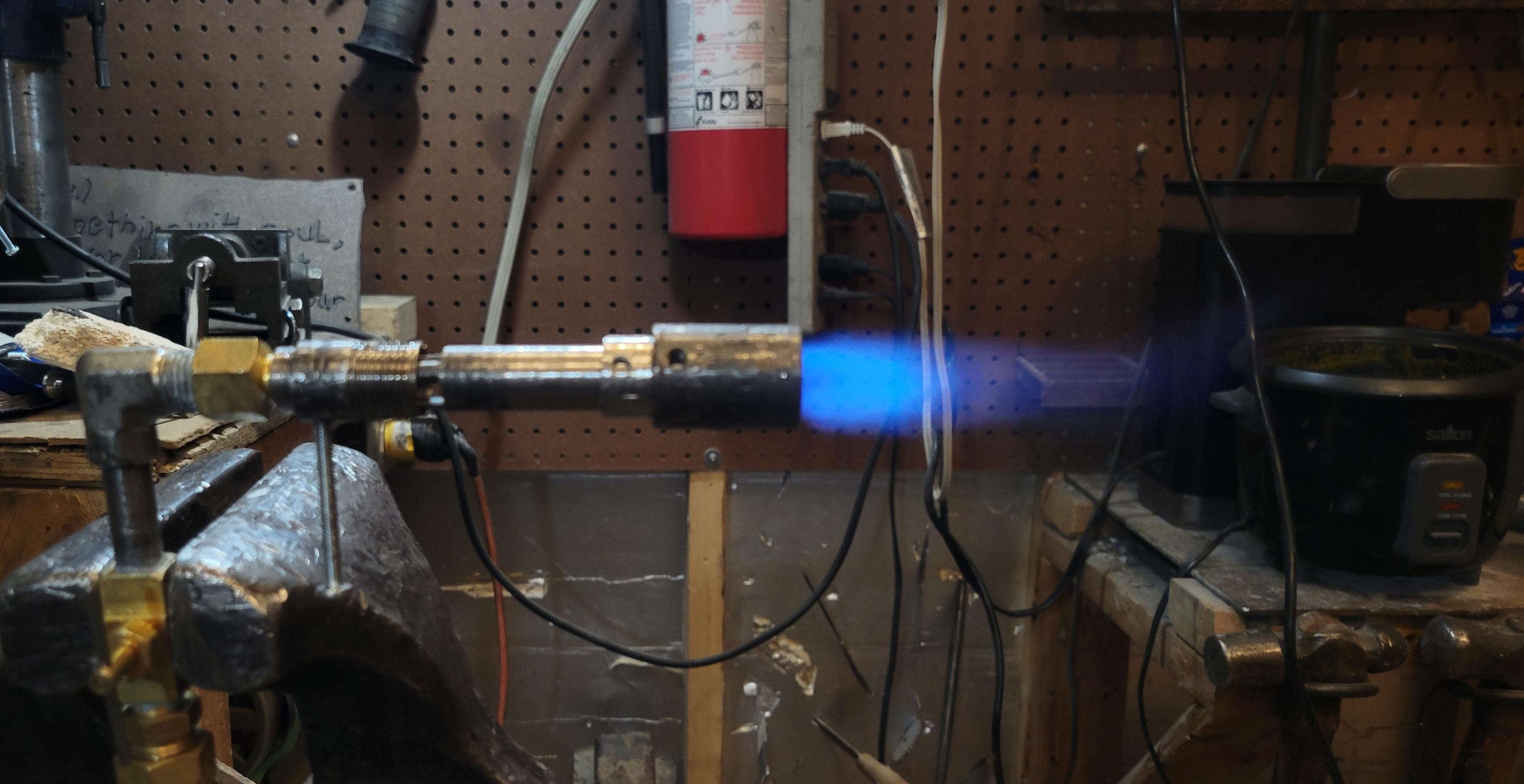
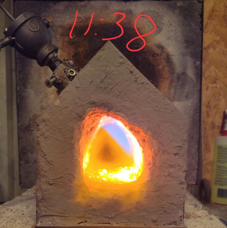
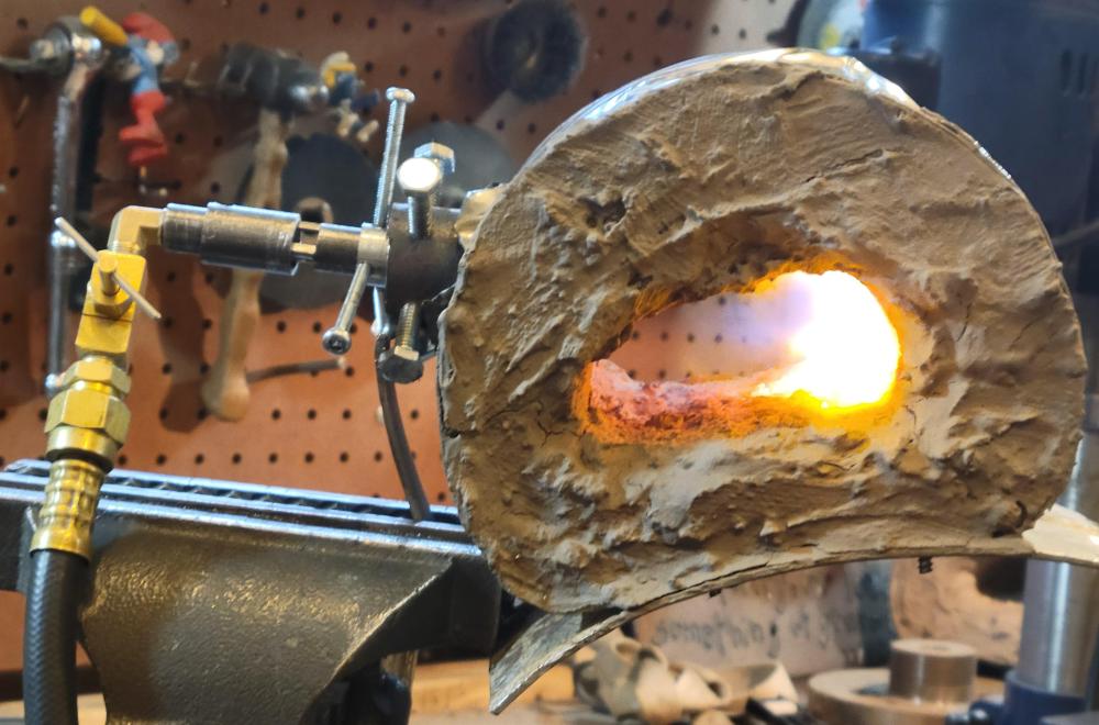
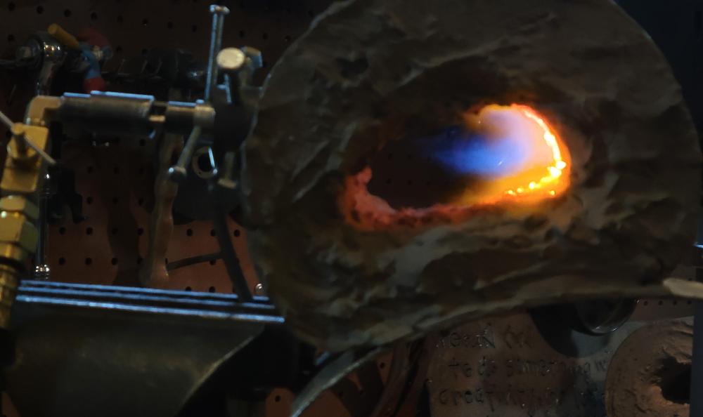
Here's the updated flame images that match the latest dimensions. Unfortunately I'm not able to slow the gasses enough to lock into place with this set up so more tinkering to be done.


-
So the updated dimensions on the micro burner stand alone post but this is the latest version of the 1/4 inch pocket rocket's flame in open air unfortunately I can't get it to lock in place once in the micro forge, the gasses are moving way too fast. I have nothing to add along the rotory tool side, I haven't had one worth a bean so I don't use'em


-
When it comes to 1/4" micro burners and options for tapping thing I'll add that one can tap a 1/4" schedule 40 nipple to accept the 1/8"npt threads. If one takes the ACTUAL ID of the pipe nipple the sizes are way out to lunch! Inside of the quarter inch is like 3/8" inside the 3/8" is 1/2" id etc I want to order some larger pipe taps.... To make a 3/8" pocket rocket I will tap the 3/8" nipple with the 1/4" pipe tap then tap up into the bottom of that 1/4" fitting (say a 1/4"npt - to 3/8"flare) to accept a piece of 1/8" sch 80 piple nipple (trim the last but of straight and the threads off a piece of sch80) to accept the mig contact tip or the 3d printer nizzle. I guess you could use a bushing but you'd want to file down the points on the nut portion of the bushing. Ughh sounds exhausting but really it's just 3 taps, trim the 1/8 and cut out intake ports. Tap the 3/8" sch 40 nipple, Tap the 1/4" mnpt to 3/8" flare or something then Tap a piece of 1/8"sch80
-
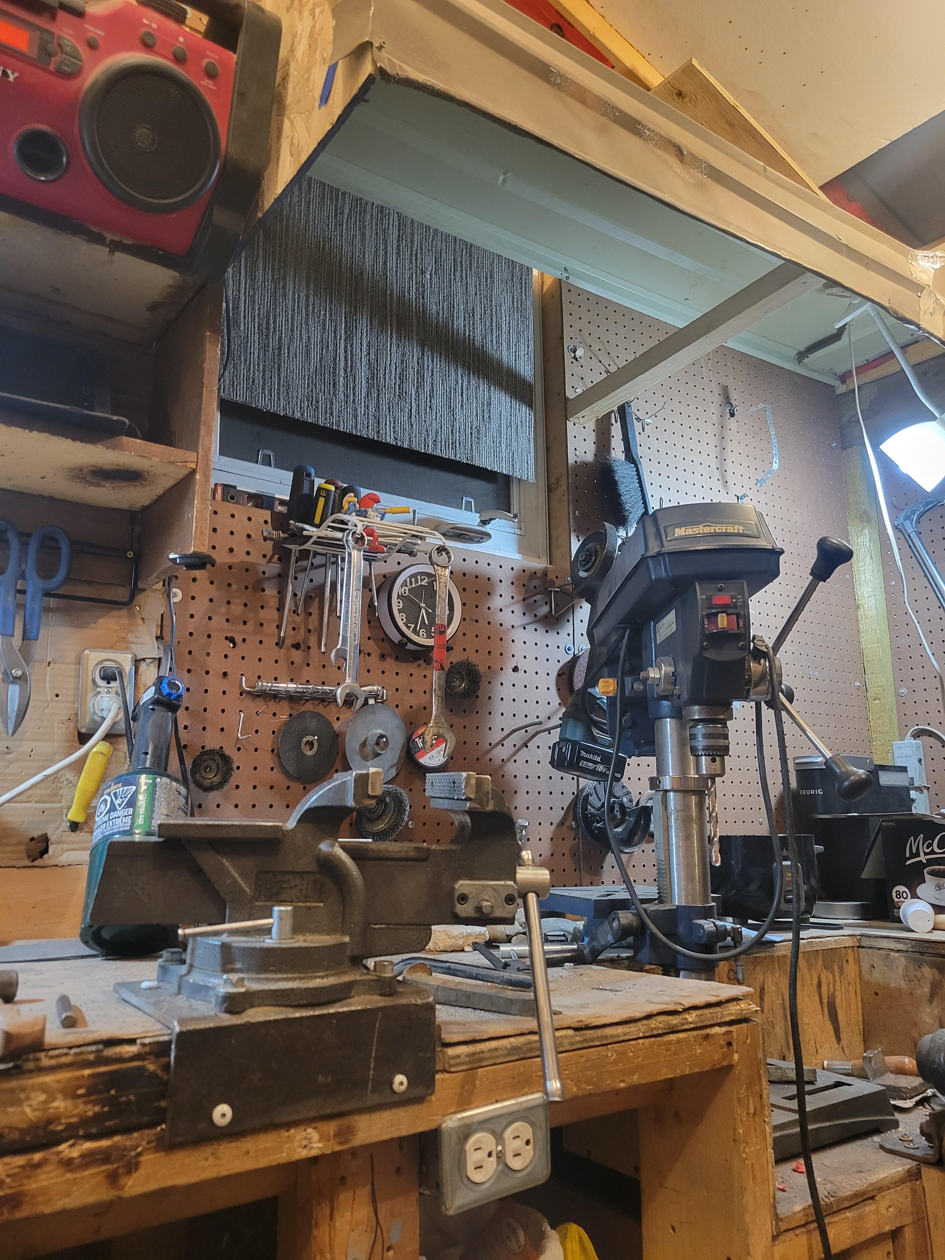
What did you do in the shop today?
Trevor84 replied to Mark Ling's topic in Blacksmithing, General Discussion
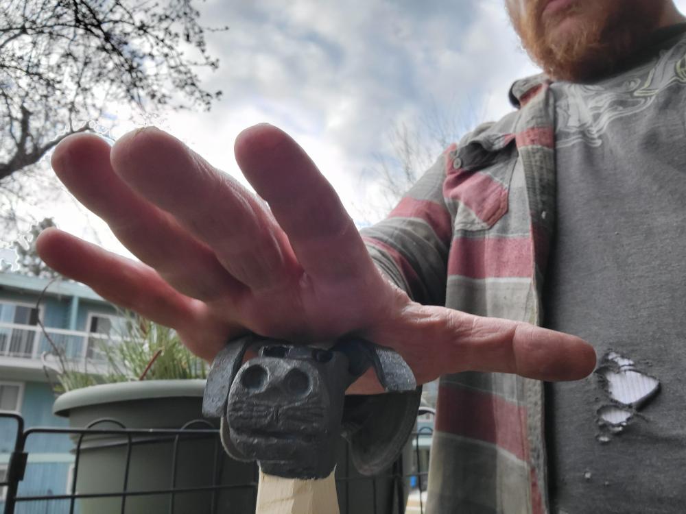
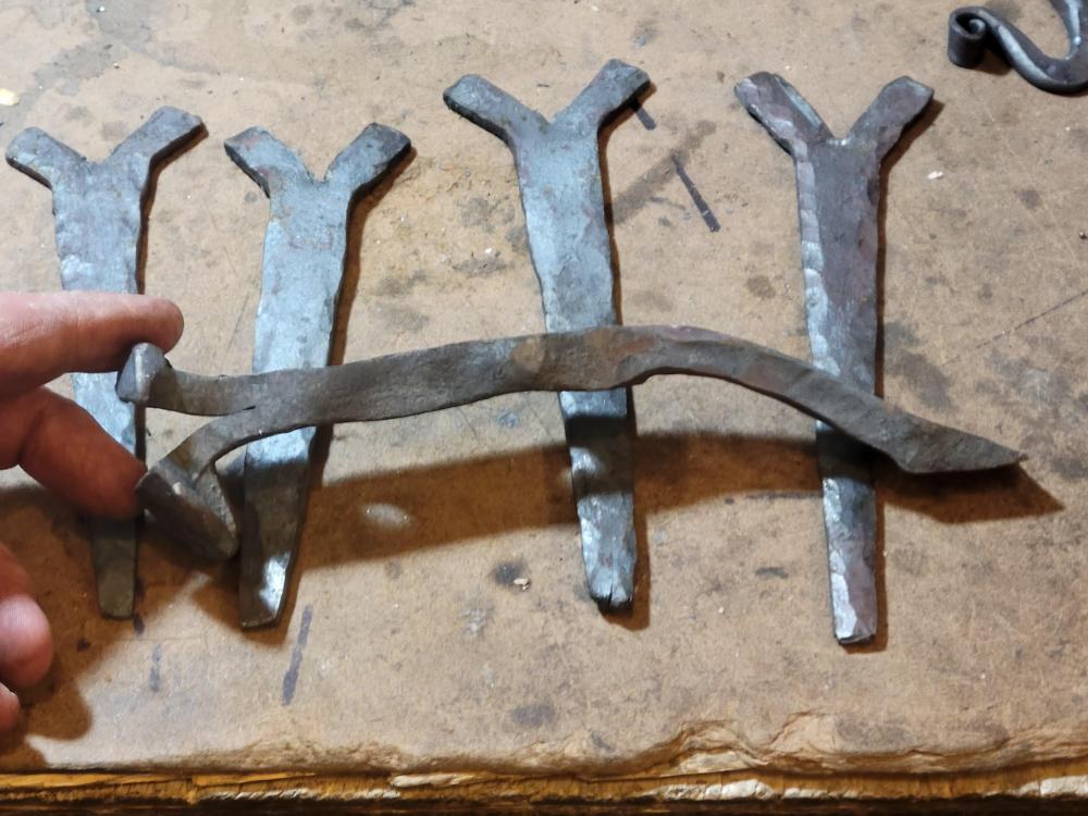
Well I fell asleep before I posted but I took inspiration from someone here and started on a cane head from a carpenter hammer A few langetts and a war hammer from a RR spike.... I haven't been at the forge in this capacity in almost 2 years and dang I live it buuuuut my back says I may have to take up a seated smithy like GS tongs.....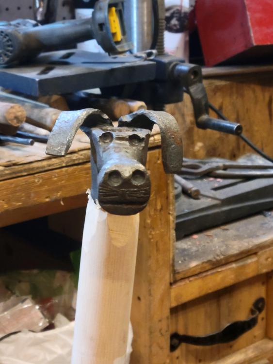
-
Oh oh oh let me join... Not tools yet but I'm sure I can do something with the axle and tierods. I don't know about this big ring.... I bought it for flat stock but it kind of tares apart if you hammer it cold..... Oh well might as well scrap it (joking) That's the ring
-
No not at all, this is a fun twist for sure a tease but fun. Aside from this super fact maging is there a free or low cost program or app that let's you simulate fluid flow? I've wanted to play with angles to see how it effects swirls and stuff.
-
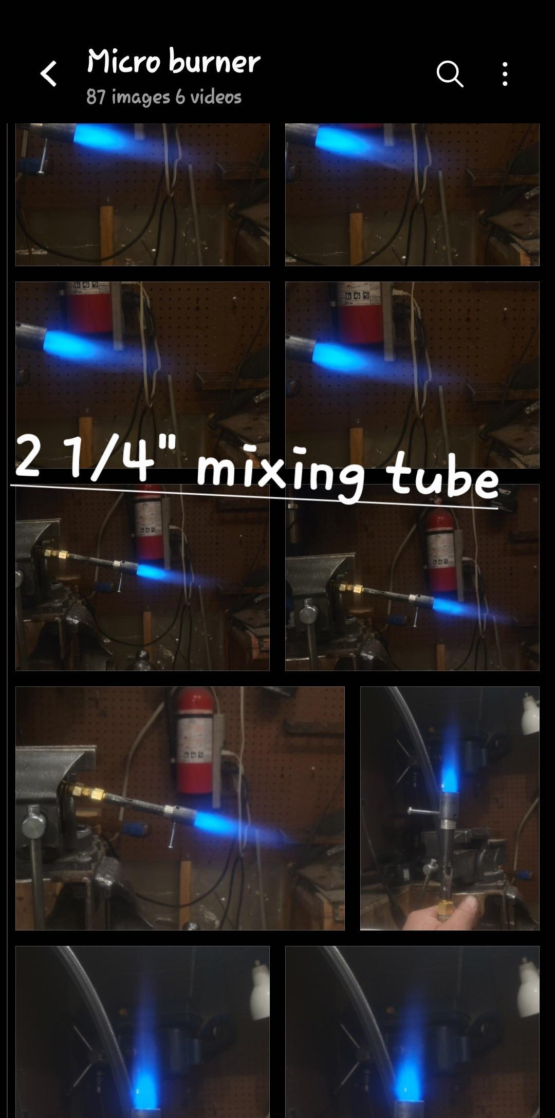
Dimensions I'm working with right now are from tip of jet/orifice to forward edge of air intakes is 1" the 3 air slot are measured back from there 3/8" and material removed to expose 3 equal openings that are 1/4"X3/8" with corners and edges filed crisp and square. The mixing tube ie forward edge of intake to the end of burner will be somewhere between 2" & 2 1/2" depending on application Nozzle is as above, a piece of 3/8" nipple reamed out and threaded into the coupler with a set screw or three. So far a choke is needed with the current dimension and distance of jet from intakes The choke is just a little piece of 3/8" reemed out with a set screw. I do think I will be shortening the distance between the jet/orifice tip to forward edge of air intakes. I will upload photos as I get them resized and orginized.... I also filmed myself making a burner tube beginning to end that I have to edit. Maybe tonight maybe a few days but not now, I got to go eat something now.
-
Hey I'm back soo sorry for the delay and geez thanks Jerry *blush* and that means a lot it really does and double because I know you don't just say what people want to hear. When it comes to the length of time that this took me to come up with I don't know what to say..... Call it a love child between gut feeling with educated guessing and mixing plans whilst reinventing the wheel. Seriously though I had made a version of a Mikey burner before with three air slots and the accelerator tip sitting just back from the throat/forward edge of the intake. They worked great and it didn't really matter where the tip of the jet sat but it was most stable where xwind could get at the gas stream ie near the forward edge. So i was sitting there wondering how to get gas into a 3/8" nipple and fiddling with a pile of parts on my bench banging them against each other like a monkey and I randomly tried the 1/8"npt tap into the 1/4" pipe nipple instead and bam it fit. I couldn't deliver the fuel as deep as I could with the larger "Mikey" burner so I stole the concept of the fuel being delivered upstream or upwind like the "Oliver" and rely on a high psi stream to make it past the opening. The nozzle I use is a mate between the Frosty straight thread coupler (not the pipe thread coupler) and Mikey's discussion on the step nozzle. So it's a mess of info jammed together but there was definitely educational type gutsumating (guesstimating with your gut) I always repeat to to beginners.... "build a few to known plans, do some reading, more reading then maybe try and wing it". I'll follow with a whole bunch more pics and what I hope to be more concise and simplified instructions or lay out. The only power tool used is a drill for reeming out the step nozzle and set screws in the choke and step nozzle and the rest with tap wrench, files and hacksaw. This is still in its beginning stages and there needs to be discussion on the dimensions I've chosen to start with and what might be better or worse. I am trying to work up ratios and relationships between dimensions like intake to mixing tube cross section is almost 3x but the top successful burners end up closer 1.5x intake to cross section area (I know it's not supposed to work like that but it's something I've been noticing as I work through different designs)
-
I will definitely try to keep simplifying it, to me tis one seems to be fairly straight forward. Tap the back end of the 1/4" nipple to take the the 1/8" mnpt. Tap the 1/8"mnpt to take the mig tip. You mark/divide the pipe into three faces/sections, file a square notch on each face just shy of 1/2" X 1/2". Or until you see a rectangle form in the center of the notch as the steel thins (inner most wall). Each square notch if deep enough will almost touch each other to make an equalateral triangle that has rounded corners. Use an awl, Dremel, drill tip of file to punch through that rectangle silhouette, that thin inner wall and clean the edges up with a small file or rotary tool. Use a larger file and taper/blend the backward edge of the intakes into a nice bevel towards the backend of the burner. Trim the pipe to 2 1/4" from forward end of air intakes Take a short section of 3/8" pipe nipple, screw it into a 3/8" merchant coupler (straight thread). Use a file or drill to clean out the 3/8" so it can slide over the 1/4" mixing tube.
-
Sorry it's three rectangle 3/8"X 1/4". Apx 3/4" from tip of jet to the forward edge of air intakes.

-
Thanks I'm hoping this can be one of those easier options. It's not nearly as hard a Mikey burner especially with the square file or a 16" bastard file on edge because the dimensions work out simple..... This is definitely inspired by the Mikey and Oliver upwind burner and uses Frosty's 1/8"mnpt taped inner for the mig and outer to mount it. I'll be making a few more over the next couple weeks and updating. I will be making a couple with some kinda handle or bunson burner type stand. I don't have real oxy-pro torches and the plumbers torch sucks for heating anything other than solder so I'm hoping this to be a reasonable in between for bending and twisting but never thought of it for jewelry.
-
Sorry Mikey, jumping in again quickly to let you guys know I just wrote up a post on a new micro burner. If you want more pics there's a bunch there but heres the gyst of it I guess.

-