1981Eagle
-
Posts
22 -
Joined
-
Last visited
-
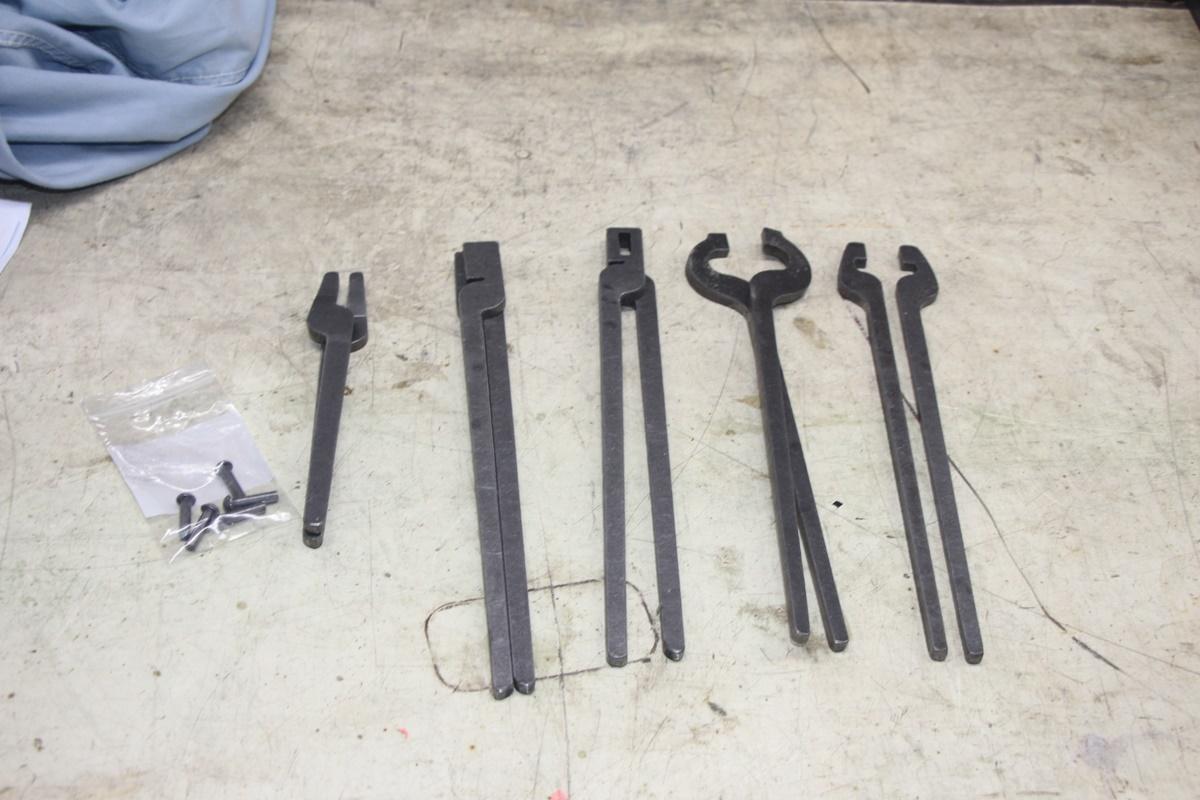
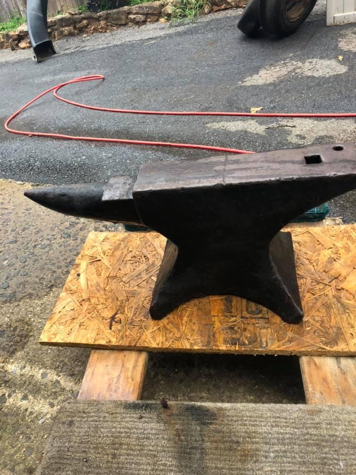
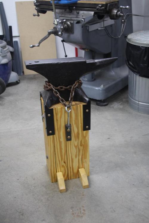
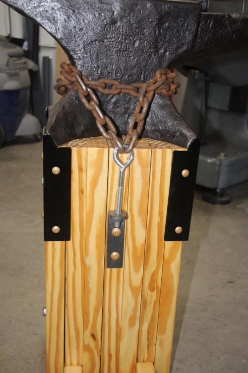
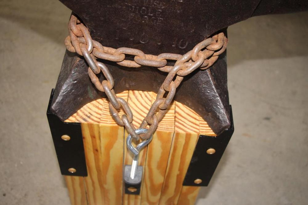
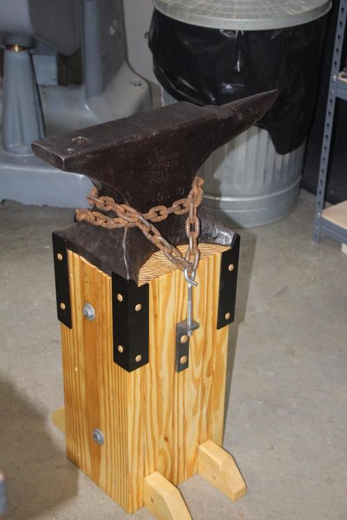
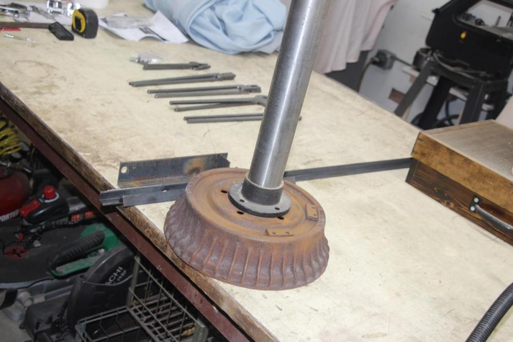
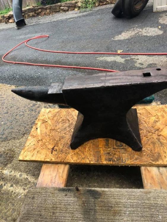
I may not be 'well on my way' ... but I am 'on my way' I picked up the Anvil and then made a stand for it. The stand is made from clear 2x10 glued and bolted together. I took some angle iron pieces to bolt on to keep it on the top. That - by itself - quieted it down quite a bit. Then with two lengths of chain one around one side and the other from the other side and eye bolts to pull the anvil down tight to the base. It's quiet and tight. Then .... I picked up a set of 'starter tongs'. They are rough-cut and probably 50 to 75% done ... the reins need drawn out and rounded and the jaws need finished then riveted ... but they are a good start. Now - I need a way to heat up the working stock. I have an oxy-acetylene set-up with a cutting torch head ... but that can get expensive ... so I am considering a brake drum forge for now ... I have a brake drum and a piece of pipe ... and I have an old hair dryer ... so I can probably complete pretty cheaply. I may want a gas forge at some time.

-
M&H Armitage Mouse Hole Anvil 122lb
1981Eagle replied to 1981Eagle's topic in Anvil Reviews by brand
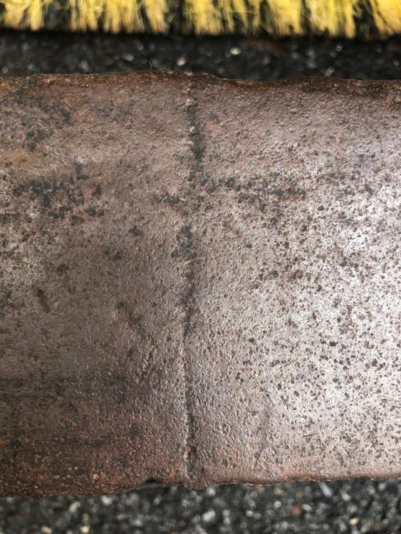
I agree ... now, when I see other Mouse Hole anvils, I am seeing that same line on many photos of them .... and mine is still forge-welded tightly and it seems to be very solid. -
M&H Armitage Mouse Hole Anvil 122lb
1981Eagle replied to 1981Eagle's topic in Anvil Reviews by brand
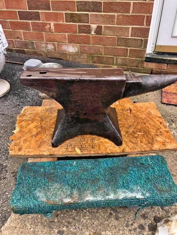
Thanks for the replies. I live in Virginia by the way. I think that 'resurfacing' an anvil is a lot like planing wood - too easy to take it off and imposible to un-do what you did ... once done. So I'll resist that thought and just enjoy the fact that its about 185 years old and it has earned the charicter is has. Next up .... a fitting stand for it! -
M&H Armitage Mouse Hole Anvil 122lb
1981Eagle replied to 1981Eagle's topic in Anvil Reviews by brand
OK ... I was 'waffling' about it anyway What is the 'best' way to remove any surface rust and old paint ... and how do you preserve them and keep them from rusting? I guess what I am asking is the best method of 'preservation' that is both 'sound' and 'historically respectful' to the history of the piece?

-
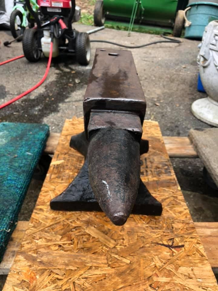
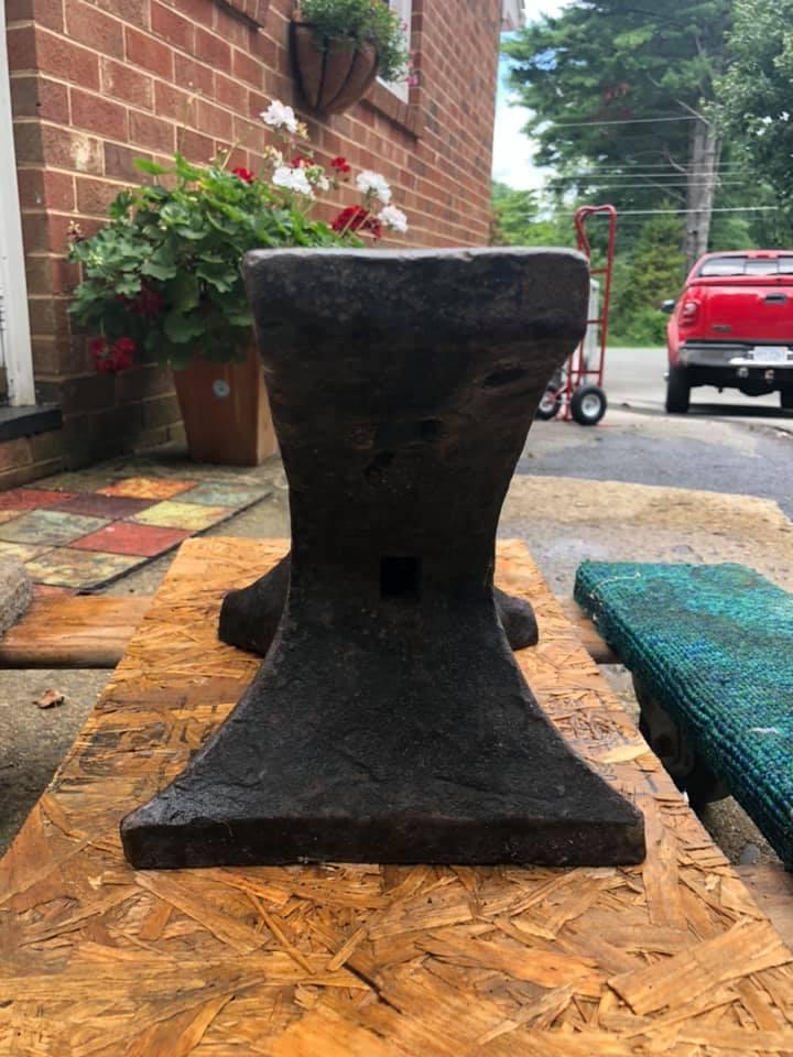
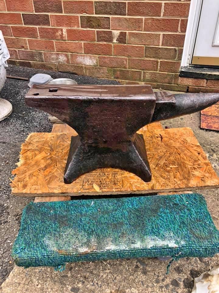
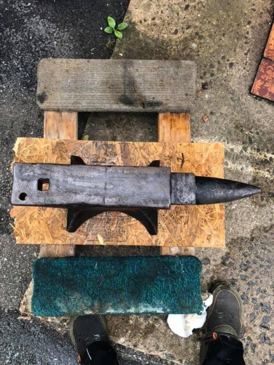
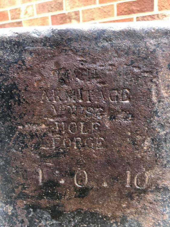
I picked up an M&H Mouse Hole Forge - it's 1.0.10 (122 lbs) My research is that it may be 1830 to 1835 era. It has a line across the top that is not a crack, but looks like a score mark when maybe someone used a grinding wheel across the face and went through the stock into the face ... but that's just a guess. It does not appear to be deep at all, right at the surface. For those in the know ... did these anvils have a steel face? I do not see a line that looks like there is, but I am not sure. Or were they one-piece wrought? I paid a little more than I wanted to, but I drove all that way and the seller wouldn't budge on the price I'm thinking of having the top ground to resurface and I don't think it's 'bad' enough to need to be welded and filled before grinding. I want to use it for small projects and maybe eventually knife-making if I get the chance. Comments welcome!
-
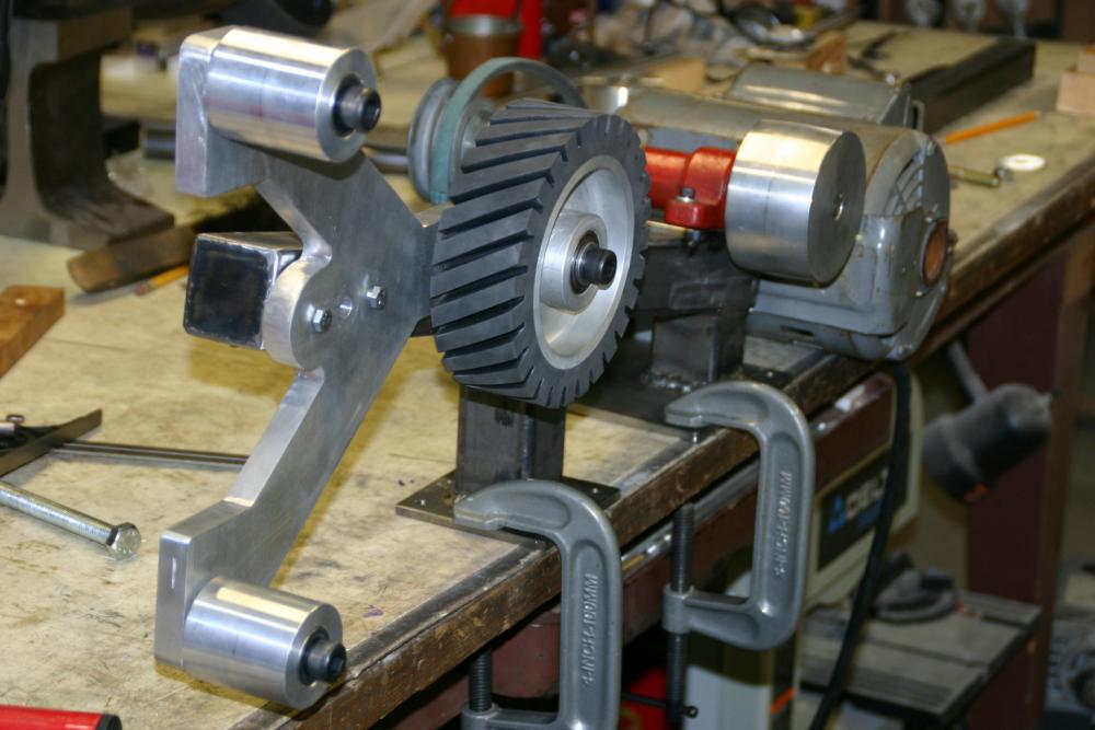
Good suggestions ... I'll likely change out the flat platten with steel, I just didn't have the correct size on hand. But it's good to get me started. Thanks for the nice comment.
-
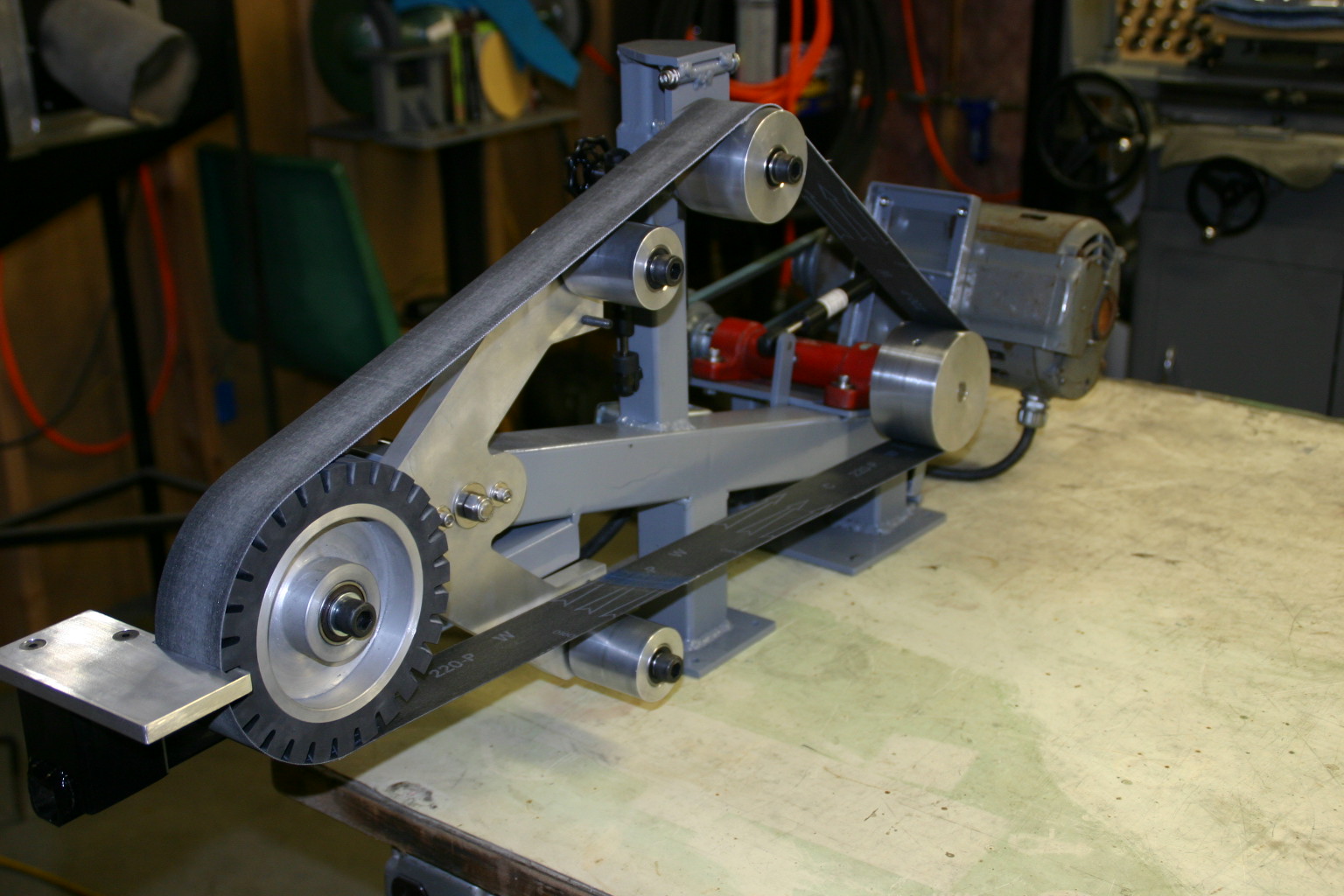
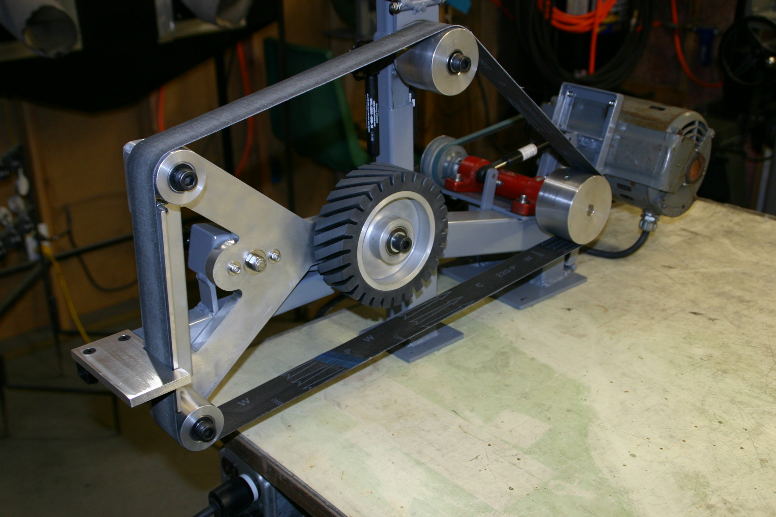
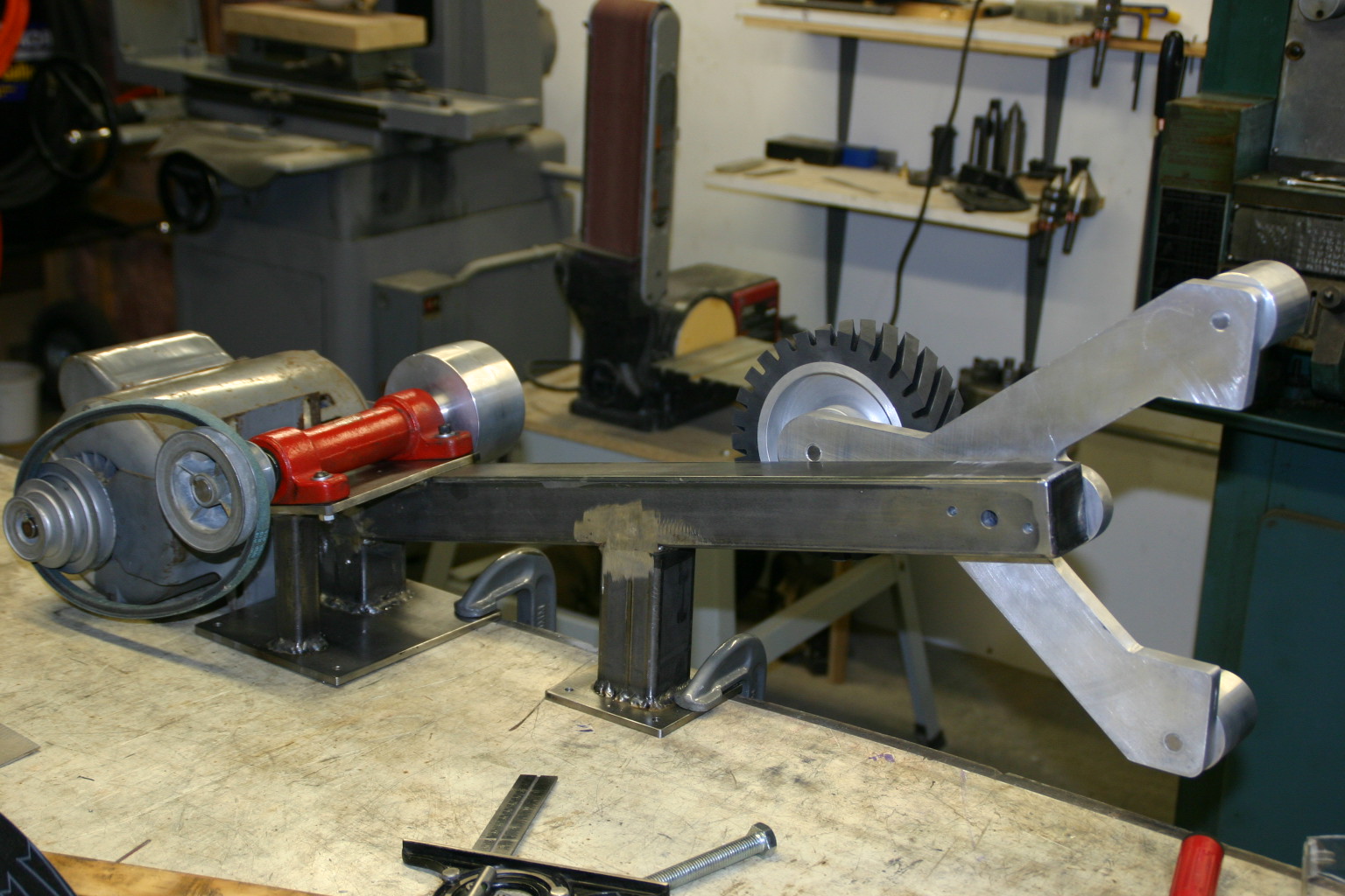
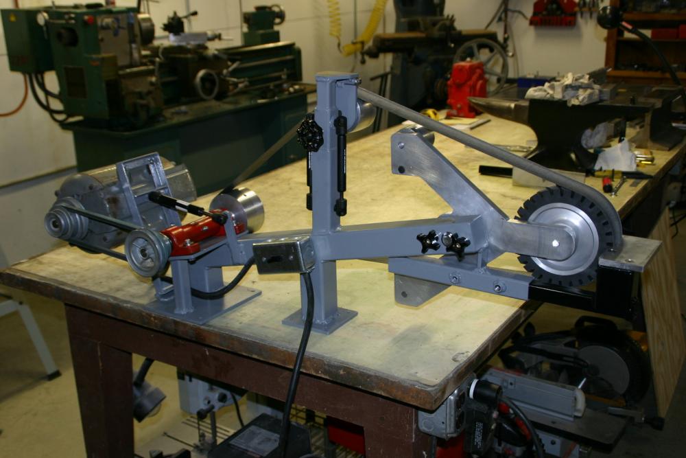
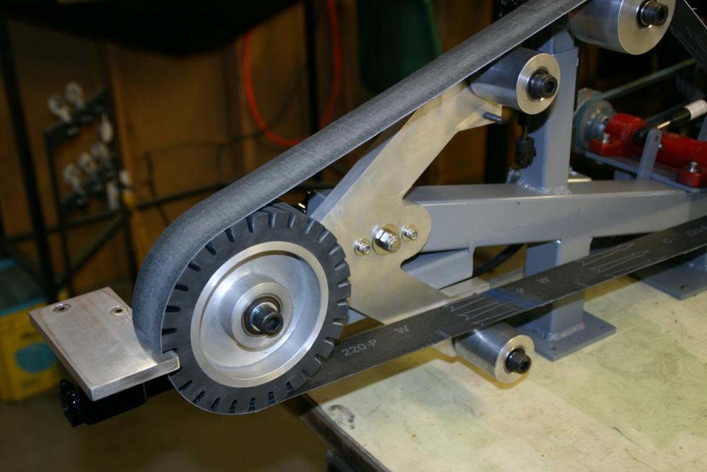
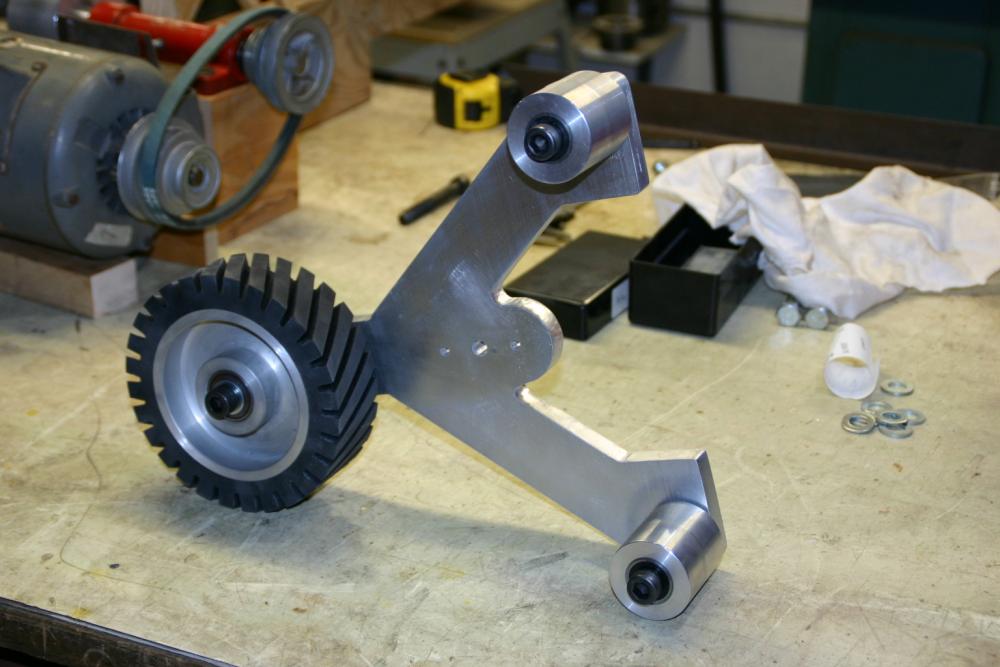
Thank you both! One choice I made early on, I could have had the machine 'low' and 'long' like it is ... or I could have brought the motor toward me, and raised the idler ... I don't know which is a better design - but my 'low' one, coupled with the rotating front, causes me to remove the angle aluminum 'backing plate' of the platen. So if you do one, you should design it so when the contact wheel is 'out' the entire platen is inside the belt! Live and learn
-
It is just about finished - just a couple more little odds and ends. I'm happy with the way it came out. It's not mounted to the bench yet, I need to make sure that it is where I want it to be. I'll probably design another front arm that holds an 8" wheel on one side and has a 'small diameter' contact wheel fork on the other. If you look carefully in the background, you can see my lathe, mill, parts of the surface grinder, pedestal grinder, the corner of the sandblast cabinet ... so this tool rounds out the shop nicely.


-
Thanks - I'll take off one of the gas shocks and see if it works with 30 lbs
-
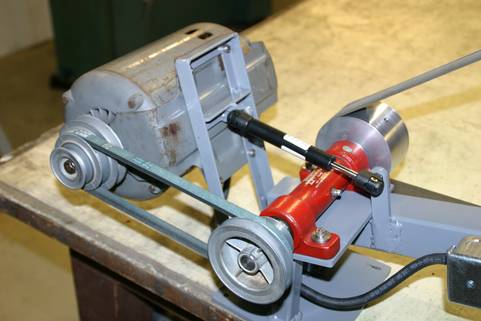
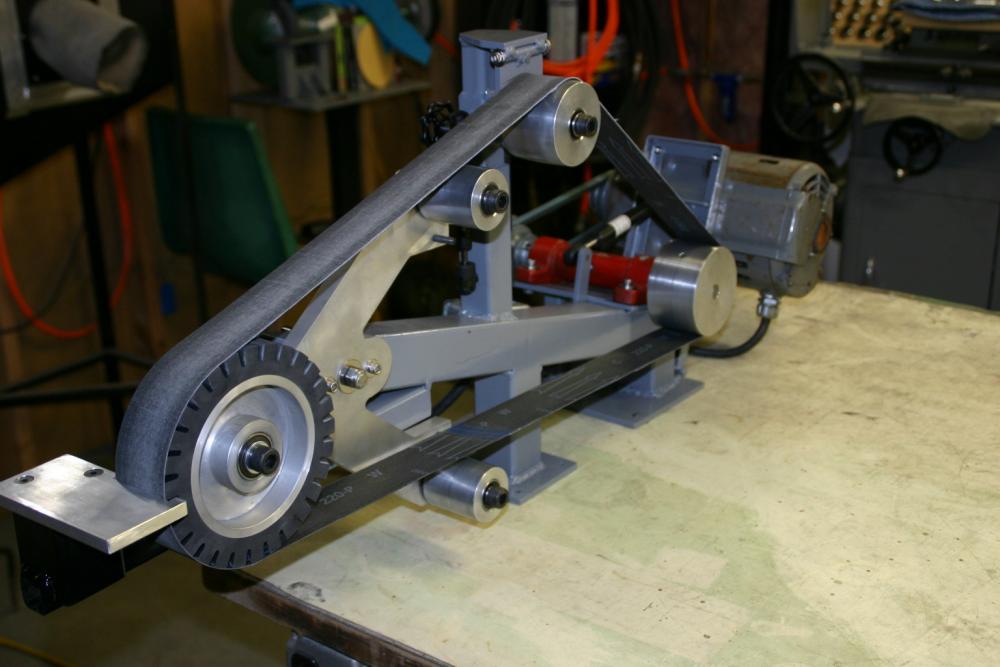
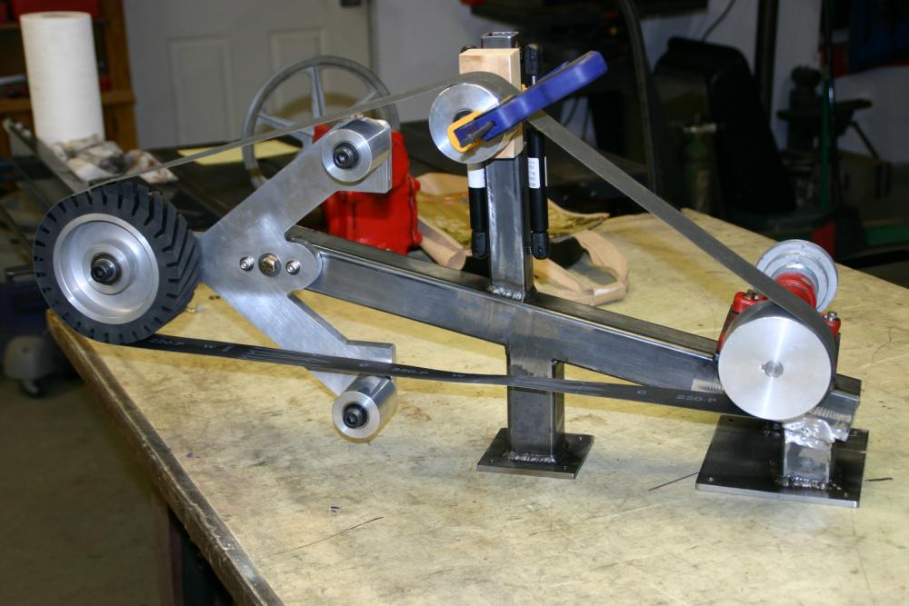
Great point - and mine are indeed cheaper cast stepped pulleys - if they create a problem, I will certainly upgrade them. I made significant progress today, no photos, but the idler/tracking wheel is on One thing how much tension one a belt is too much? Or is there such a thing as too tight? Mine 'twangs' like a bow-string and it has 60lbs of force on it I still have to make a backer for the belt for the platen - and a rest. Then a rest for the 6" contact wheel. Last is the motor mount. Then final finish work and paint.
-
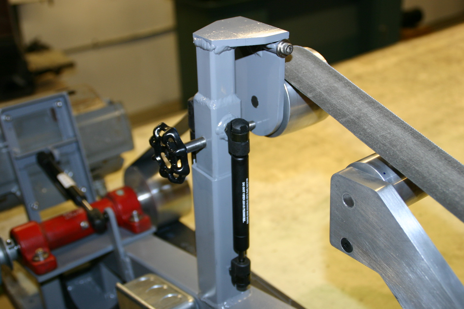
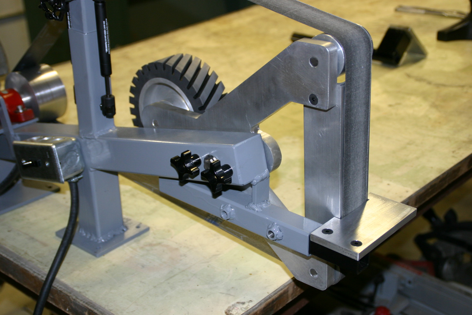
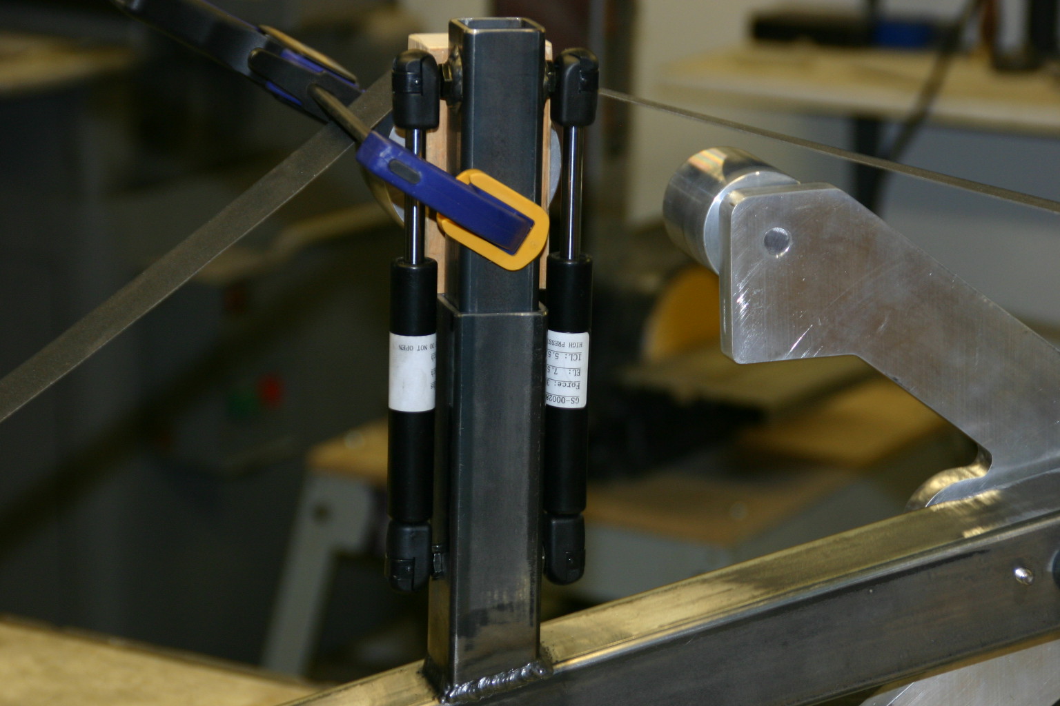
Thanks John ... In keeping with the 'interesting design' concept, I went with dual gas shocks on a telescoping mount, rather than a hinged arm with springs or shocks. Now I will 'work out how I will make the idler wheel / tracking adjustment. I'm liking it so far ... some of my welds aren't pretty, but they are solid enough.


-
I got my first order of metal. The main beam is 2"x2" and I put it at a 12 degree angle. I have two 30lb gas struts on the way for a tension arm. Left to do is the tension arm with tracking control. Then the motor mount and drive-belt tension control. Then a bunch of finish work and paint and it's ready to use.

-
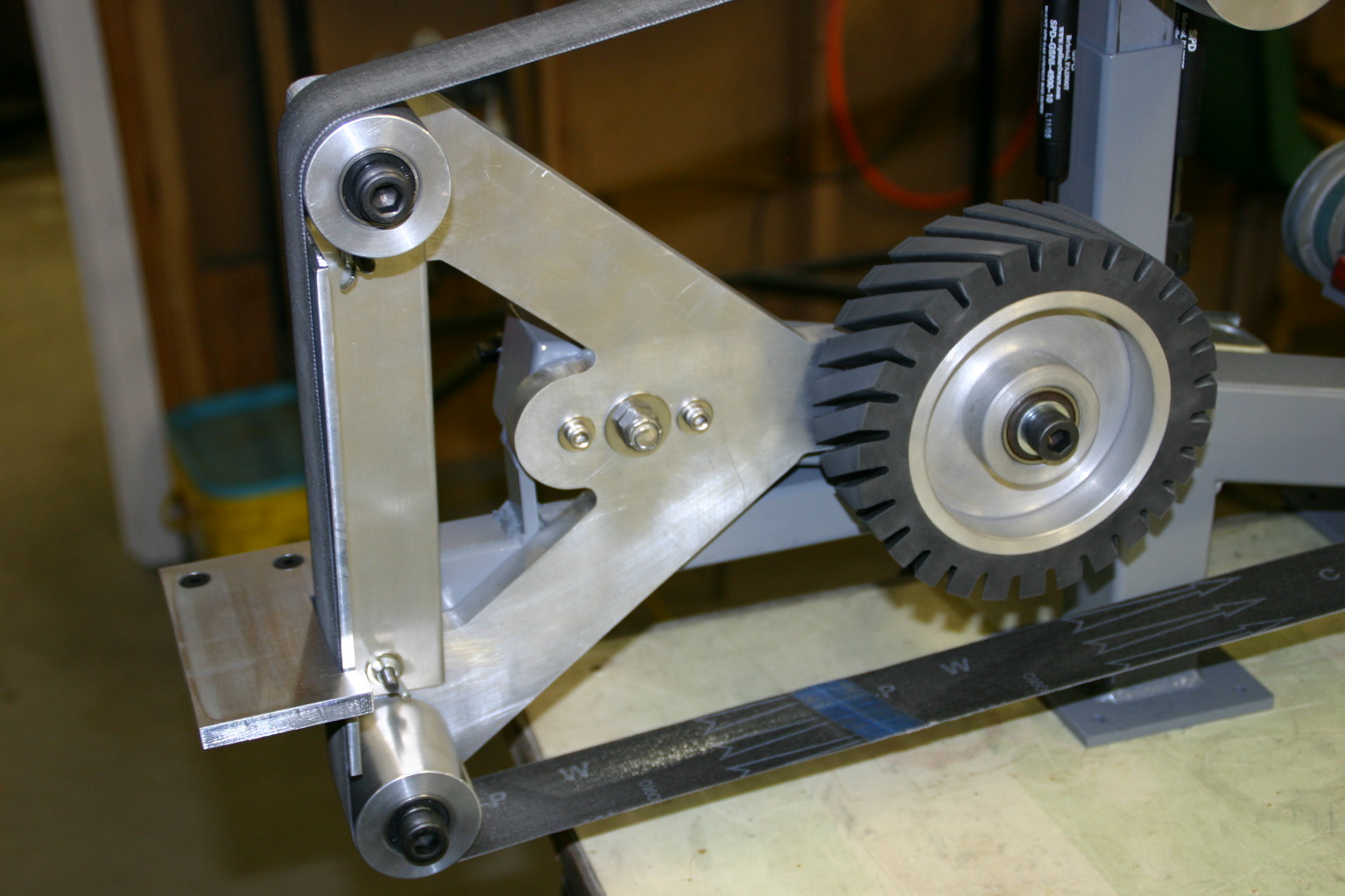
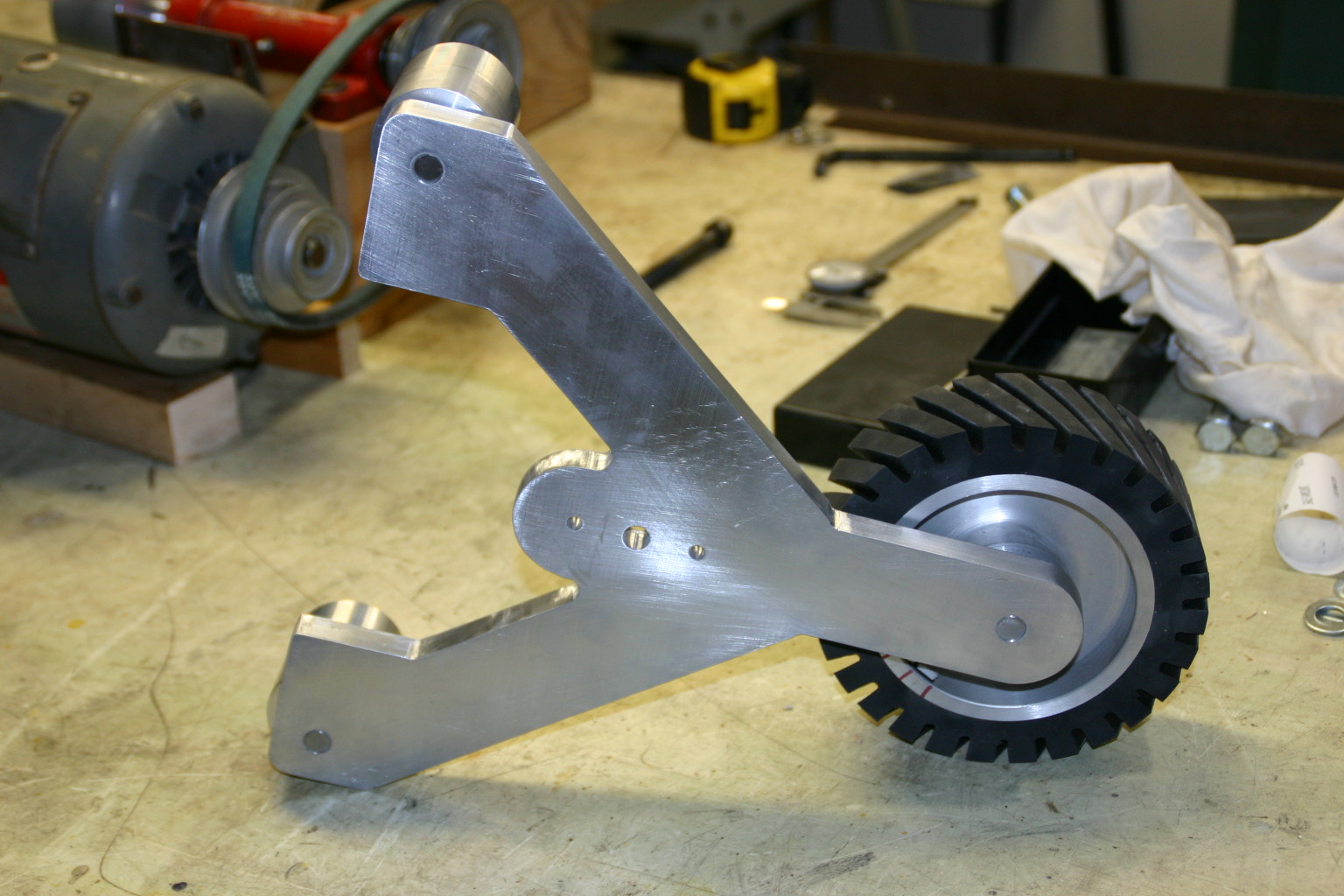
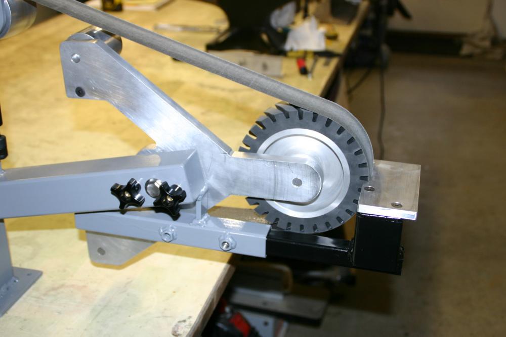
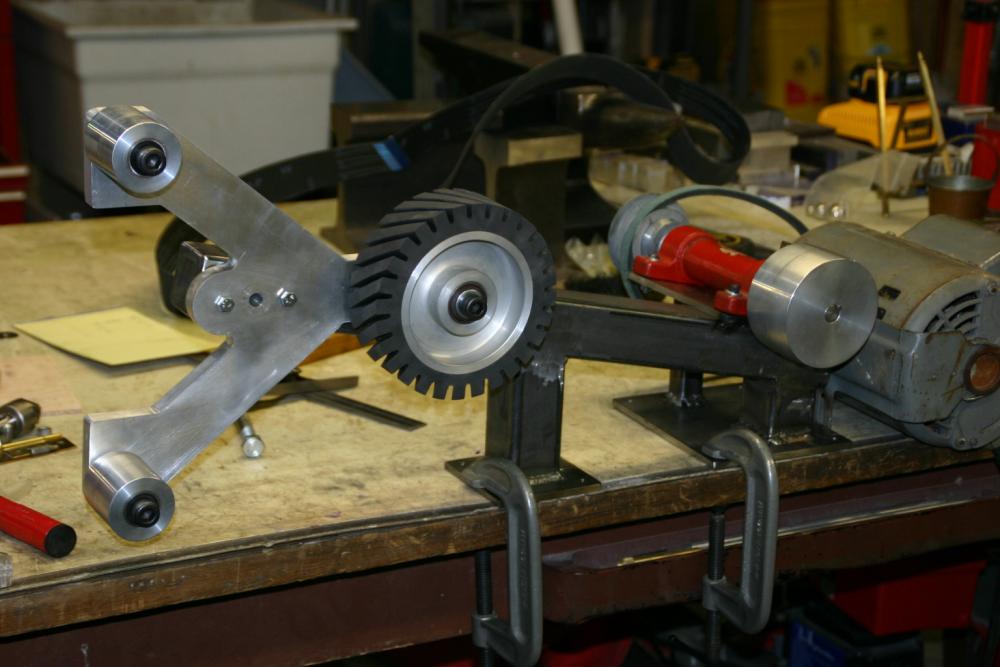
A lot of work - and a lot of left over 'scrap' that is going to be quite usable - and the platen/wheel armature is 'done' with the notable exception of a backing plate behind the belt and the rests for both. It is 5/8" 6061 AL - I figure it will be plenty strong enough for this application.
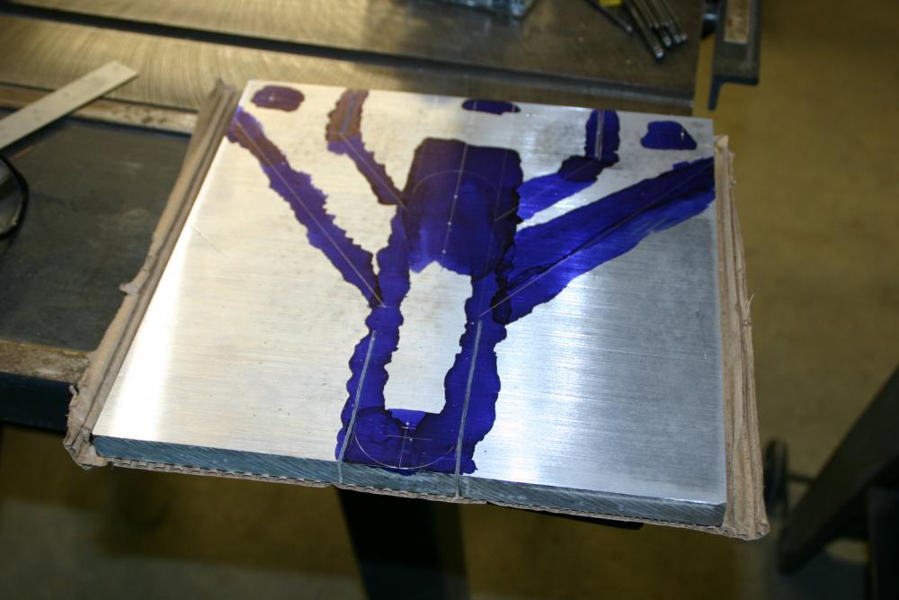

-
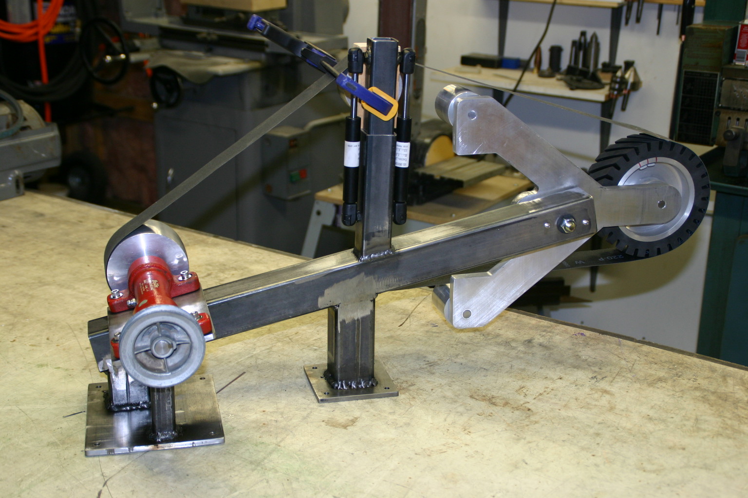
The two wooden 'struts' will be replaced with gas struts - so that should take care of uniform tension. The top idler will have a tracking mechanism too ... probably a 'hinge' of some sort with a handle that allows me to pull the gas struts down and applies or reduces tension on the 'hinge' allowing for tracking adjustment. A couple things I didn't fashion out of wood - too intircate and I have a pretty good idea in my head of what I will do.
-
Yeah - but I had to work out where the pivot point needed to be so that the belt tension would be about the same no matter which one was 'out' I still a have to make a 'backing plate' behind the belt and a rest (for both sides) The motor set-up will be a 1-1/2 HP three speed stepped pulley