jlpservicesinc
-
Posts
5,754 -
Joined
-
Last visited
Content Type
Profiles
Forums
Articles
Gallery
Downloads
Events
Everything posted by jlpservicesinc
-
liability form
jlpservicesinc replied to Timber Ridge Forge's topic in The Business Side of Blacksmithing
Any lawyer is going to pick apart any document that is out there for liability exclusions.. It's their job and the more they can up the money return the more they can make.. Any honest person will not think 2X about doing anything if things have been explained to them before hand and that is what integrity and honesty should be.. I engaged in the activity on my own with full knowledge of it being or having dangerous times... No ones fault but my own, if I cut a finger off on a hardie left in the anvil or hit a bar in loose fitting tongs and lose my teeth or smash a finger crushing it.. Etc , etc.. But then people will get injured and start looking for a way out... Talking to friends and the friends will say Oh, that is terrible you got hurt while at the workshop.. You should sue for injuries and damages... Ah, how long are you going to be out of work for crushing your thumb.. 11months.. Better off cutting the finger off or loosing some teeth.. I smashed my thumb between 2 metal plates nearly 2 years ago and it's still healing.. Was painful for nearly a year each time I used it.. But I can't take time off from work so just dealt with it.. Still has a spot in it where it won't work with the cell phones touch screen as the tissues are different.. LOL.. Anyhow,, Its the whole " Make someone think safety protocols and standards were not followed" and it really needs to be stressed time and time again that there is a group safety meeting before each class especially the first class.. I used to teach martial arts, scuba diving and pistol defense classes and each one used a standard form.. The one for the scuba and martial arts covered just about all bases except being blown up by a missile or being carried off by a whale.. In scuba I know 5 skilled people who have died in simple dives... I know a few in the martial arts (not my classes) that got a finger cut off or stab wound with a knife or sharp tool.. It really becomes what the suing person believes they can get out of it..... Not one of the people I know in the martial arts sued for the injuries.. but in the SCUBA the family members left behind did sue.. They all pretty much got nothing as the people died from what was deemed natural causes vs equipment failures.. But again, it becomes who accepts responsibility for themselves vs laying it onto someone else's back.. This is basically just a can of worms and again a Lawyer will tare anything apart.. But at least it's a start.. (for the martial arts I used to show slides of fingers on the floor, ears torn off and the such... LOL.. Not one of my students has anything more than a fat lip or a black eye or a skin prick from a sliver while climbing.. here is a copy of the Martial arts waver... I used to have all students sign one and get it notarized with witness on their own time after the first class which was very low key.. At each special session each student would have to sign a new one with the other students signing it for them as a witness.. GENERAL LIABILIT blank for web.docx Oh, one other thing I nearly forgot.. We would go over the sheet in class together and talk about and discuss each box which needs to be initialed before even starting class.. -
Are these Italian or French in pattern? The Italian ones I have seen have more stout bases which are nearly solid.. The French I have seen look more like what you have there.. Curious myself..
-
Heck yah.. That is serious hammerin fun.. Will you find a way to bolt it in or a way to retain it in the stand?
-
Lots of places where the industry left and the artist took over.. Mass Moca is another example..
-
@neilyeag sorry but from what I can tell the weld seams in the back or heel show vertical lines.. So this is a composite or a laminated anvil with plates welded together to get the size and mass? and then the top plate welded on? Were the plates used in the base through welded or just around the blocks as a perimeter weld? Were the welds scarfed out? Gouged for a deeper penetration weld bead? Was the top plate heat treated after welding or was the whole thing welded out of the same material as the face? Inquiring minds would like to know..
-
You said leg vise which on a blacksmithing forum means a blacksmithing leg vise.. Which is totally different than a woodworkers toe vise.. I call it a toe vise as it has a little toe that sticks up to catch the edge of the board.. A shorter handle is all that is needed when wood working..
-
No on the wrap around the pipe.. YOu would use what ever your desired handle thickness will be and then the PI formula in the video would be what you want (less the thickness for welding losses)... If you have an 8" width jawed leg vise.. You will want a lot longer handle than 8" diameter and believe it or not.. Ideally you want a scalloped square or octagonal handle vs round on the handle as you described.. You need something that will fill in the the bends of skin at the joints if you want to put out maximum torque in a circle.. If your vise is an 8" jawed leg vise the handle should be straight and roughly 2ft long out of 1" round stock.. Anything smaller or shorter you will be wasting your time.. If you had a 6" machinist vise I could see using a round ring with spokes to crank on as these vises are not as heavy duty as a leg vise..
-
Hello @Elciteeve the guys pretty covered the bases.. My question is why do you need it to be a certain size? Rectangular would be much better to start with vs round (1X2X12".. Round stock in order to get it round again you would have to forge in the sliver of a corner on 2 parallel faces (tough to do ).. Remember that round stock flattened becomes an oval and then it becomes a round sided flat.. This oval or round sided flat if you want to make it round again is a big waste of time when you consider starting with rectangular will give you a square bar and then to forge to round is easy.. Now from what I gathered you want a 8" diameter circle? Here is where I will differ from the other guys... I would not hesitate taking on the job if I were using 1"X2" but not 2" round.. Unlike in the video where I use a flat hot chisel I would mark it out cold fairly deeply.. Then I'd use a round edge hot chisel.. You will want a long handle on it as your hand is going to get really hot over that chunk of steel.. Once just about through I would switch to the flat edge chisels to get rid of the choppiness of the round edged chisel.. The reason why I would do it is " It's a short section.. You figure after upsetting both ends to make up for the material you will lose in punch and bend on the ends you will end up with a bar that is total length once upset about 10" long.. And you will then only be slitting about 8" total... That is pretty easy in 1"X 2".. Any larger than a 10 or 12" ring from that sized material I would think twice without the correct tongs and such.. The 200lbs anvil, a vise, a couple of hot cut chisels, a face plate on the anvil, a round punch and one other thing is a drift to drift out the split in the ring.. I used the hardie in the anvil, but for something of this size you will need to drive a larger object through it to open it enough to get it on the horn of anvil... When you open the ring have it as hot as you can the full length... As a beginner, If you do pull this off it would be a major feather in your cap.. Anything over 3/8" for a beginner is a major undertaking and this ring while simple and straight forwards with that size of stock it will be tough.. I would suggest making one of a smaller size and then applying what you learned to the larger ring... I to used to be poor as dirt what I mean to say is dirt even cost to much.. so I get it and it's the reason I became a better blacksmith.. I knew of no short cuts only hard work.. This hard work translates into learning the best way to do something.. I'm excited for you and thanks for the inspiration.. If you have any more questions just hit this thread up... I check it daily..
-
Wish we had plus 1 on the threads.. Well said..
-
Treadle hammer mechanics?
jlpservicesinc replied to Blister Fingers's topic in Power Hammers, Treadle Hammers, Olivers
If we still have snow at the spring meet I won't be coming as I'll be in the cryo sleep chamber waiting for the world to warm up.. -
Treadle hammer mechanics?
jlpservicesinc replied to Blister Fingers's topic in Power Hammers, Treadle Hammers, Olivers
No Power in the trailer.. -
Here here and cheers to all. Happy New Year..
-
Treadle hammer mechanics?
jlpservicesinc replied to Blister Fingers's topic in Power Hammers, Treadle Hammers, Olivers
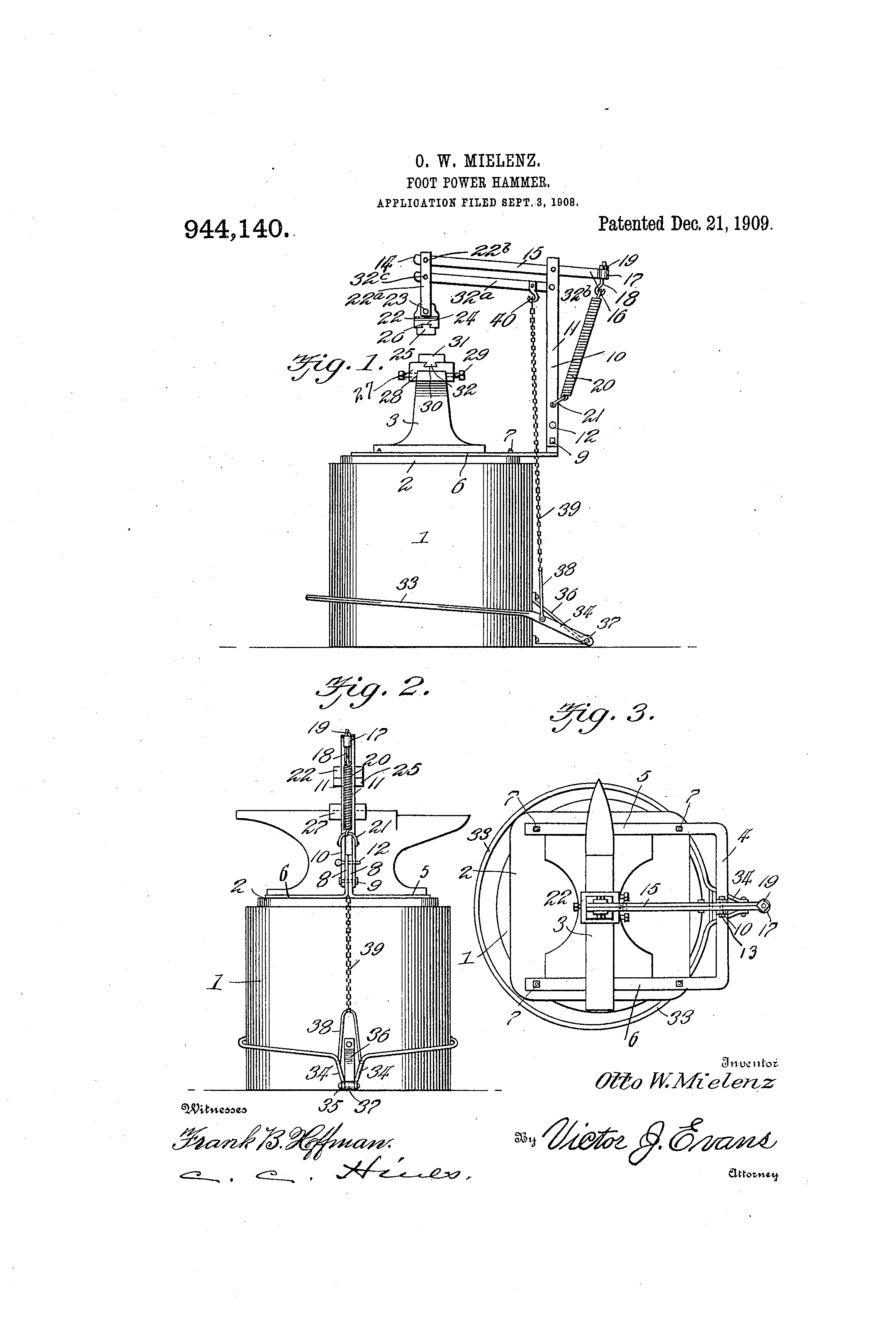
You my friend have started down the slippery slope.. Keep in mind the limitations such a hammer offers.. The hammer I will be designing for all intensive purposes have a neutral " No " spring point in the travel.. Springs on top to increase or reserve energy from the up stroke and then with feeder or cushioning springs which will help accelerate the head back upwards.. Not sure if this bottom assist spring will be air or not.. Basically a balanced setup with body weight controlling how hard it hits but also speed with which it operates and hits.. Faster the operation the harder it will hit in free forging mode.. ( I do not plan on it being a forging hammer ) this would merely be for assistance.. 10lbs X 10FPS vs 1lbs X 100FPS.. Same energy 2 totally different blows with the difference being in penetration and mass moved per strike.. Ideally you would want to figure out what you actually want to do with the hammer.. For me it's for when I need a 3rd hand (welding) or for finishing up on swages after hand forging to nearly the desired shape.. it will pivot out of the way of the anvil so as not to obstruct the anvil or stand in any way when not in use.. I figure it will weigh about 300lbs when finished.. I would suggest you decide what you want to do with the foot operated hammer.. Then engineer it from there.. 5:1 or 6:1 ratio Basically we are talking 2 different ideas as mine will be a foot operated sledge hammer vs a treadle hammer as Designed on ABANA.. To clarify: Heavier the head, the slower it will move.. Lighter the head the faster it will move.. Less mass to overcome... a longer stroke or travel will increase the speed for a given size or weight up to a limit of what can be pushed on.. 34" inseam gives me about 12" of travel in the pedal.. This ratio will = the leverage point of the beam from the swivel of the head/handle.. On todays treadles they are retaining the head at the very top of the stroke or nearly so... this limits snap unless you are using the spring arms which have limits as to flexion due to vibrations in a ripple effect.. It is not a clean return stroke the springs flex and then return after several vibratory waves back to straight.. What is your base? This will determine head weight.. I believe I will be using a hydraulic source to raise the whole assembly but this is where the engineering and R&D factors have not been ironed out.. -
Treadle hammer mechanics?
jlpservicesinc replied to Blister Fingers's topic in Power Hammers, Treadle Hammers, Olivers
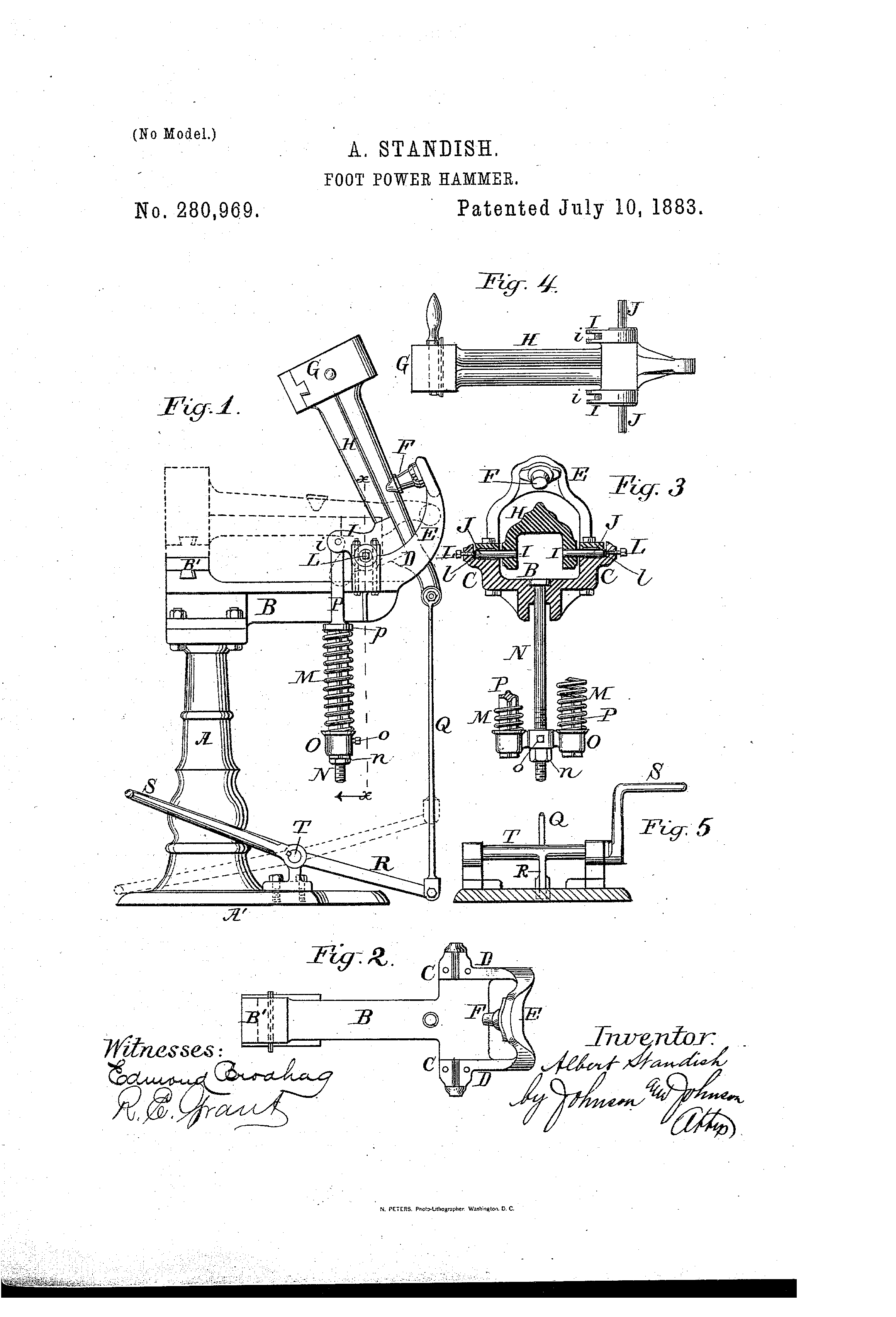
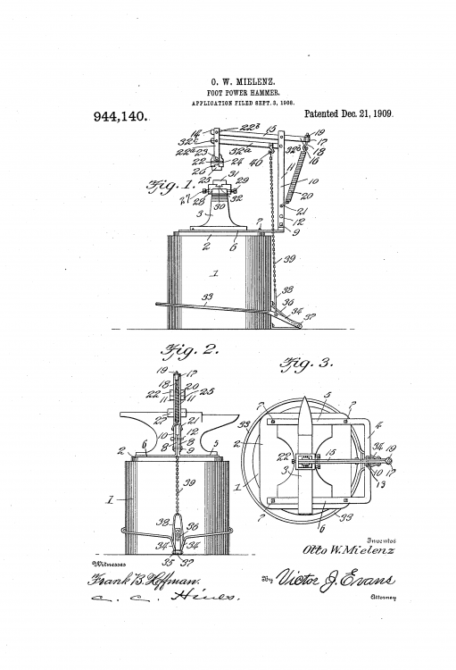
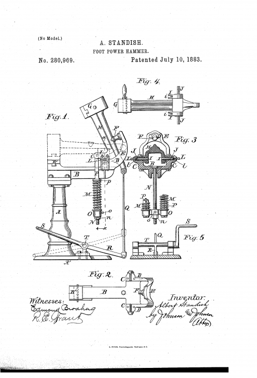
Only the first pic offered a remedy.. both other hammers had no fixing.. The stanndish hammer had dies you could replace.. As to foot hammers the simplicity or complexity of design is left up to the inventor and imagination.. for my hammer it will have several advantages of which will be a floating bearing post which will spring loaded so with just a quick step on the lever will adjust strike height up or down several inches.. It will also have a one strike function which will mean I can stand on the pedal without it letting go till it reaches a certain amount of pressure and then it will strike hard single blow.. Next will be a counter balance spring which will add to the head snap on the way up then back down.. and then lastly it will have both a soft and hard connection rod so I can control the tup/head exactly with full feedback.. Or if I need to during heavy repeated blow it will cushion the repeat strike with a soft connection.. -
Treadle hammer mechanics?
jlpservicesinc replied to Blister Fingers's topic in Power Hammers, Treadle Hammers, Olivers
So the linear hammer came about to get as straight a blow of the tup as possible.. This advantage is offered for different thicknesses with no head adjustment and also why the newest addition with skate wheels came about.. The old good foot hammers had an easy way to adjust for a flat hammer strike to any distance.. The problem is when you switch tools you have to move the head again.. This created a lot of complexity in use.. Ideally a foot hammer will have a snap when used fast and a full stroke when used slow as with most of them you lose about 50% of the swing when used in a one strike function.. The first pic is my favorite and is what I will be basing my foot operated hammer on for the trailer.. another member on the forum here and I had discussed a foot hammer in great depth with the functions it would need to be truly useful but the thing to remember is " It's foot and leg operated".. How fast and hard can you go standing on one leg.. If you have ever used a foot powered grinder it will all become clearer.. The Stanndish Hammer was offered for sale in a lot of the rags of the day.. I don't see a way to adjust the head distant or angle.. There were a whole bunch of these patents offered.. This was just from the first lookup.. They had them with air cylinders, rubber bumpers etc, etc..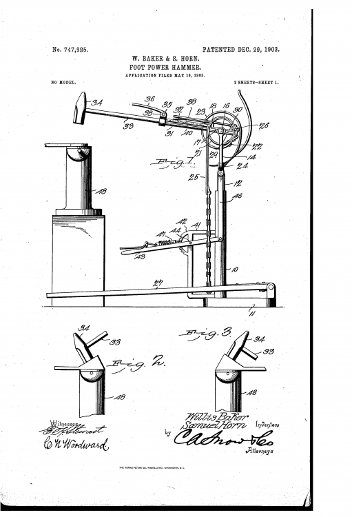
-
Treadle hammer mechanics?
jlpservicesinc replied to Blister Fingers's topic in Power Hammers, Treadle Hammers, Olivers
Changing the leverage point only changes the ratio of speed,and pedal travel moving to this type of arrangement would increase speed of the head for a given foot distance.. Also would shorten up the distance the foot pedal travels.. It would also change the ultimate pressure you could offer to the tup as it is closer to the pivot (or shorter on the lever).. Shorter lever = faster (More snap) but it is also pretty complex when you add in friction losses and such.. I've made spade bits for steel and they work very well.. The geometry of the cutting edge is most important.. In smaller sizes they actually drill quite quickly.. -
What did you do in the shop today?
jlpservicesinc replied to Mark Ling's topic in Blacksmithing, General Discussion
It looks very nice but the first time you use it the face will be all marred up.. -
What did you do in the shop today?
jlpservicesinc replied to Mark Ling's topic in Blacksmithing, General Discussion
-2F at the 4th stop of the day.. 16Hand Racking horse.. done outside on the driveway.. ICE frozen in them feet like it owns the place.. 15 Horses done today and it's still -1 at 2:43pm EST.. Can't wait for the spring fling.. Actually Can't wait till I can get out in the trailer and make another "How to" video.. Sadly i ruined the last 2 I shot on 2 different occasions as I learn a new camera.. I was kicking myself as 2 of the cameras out of the 3 had great footage and I deleted all the footage from the anvil front view on accident.. Stay warm.. I looked into the trailer and it was -2F so no video's today.. I never complain about the heat.. I rarely complain about the cold, but I complain about the snow every chance I get.. In the farrier game you go from 0 to 100 awfully quick and you just get all sweated up and it's off to the next job to start over again.. Hot, sweaty, cold, hot, sweaty cold.. Rinse repeat.. This time of year the snow in and on the feet leads to a lot of moisture and this leads to frozen tools which you have to hold and while you can add layers what do you do when you are down to a shirt, and pants and it's -10F out and it's the sweat that will kill ya.. First rule of winter survival.. don't sweat to much or else your gonna freeze to death.. I have never found the right balance of clothing to cold vs sweating.. Mind you I'm a little plumper than I used to be but still have a 30" waist so there isn't a lot of frost proofing built in.. See how lucky I am.. I got to complain again.. LOL.. -
What did you do in the shop today?
jlpservicesinc replied to Mark Ling's topic in Blacksmithing, General Discussion
-4F here this morning.. what I would give to be complaining about the temps being to hot.. -
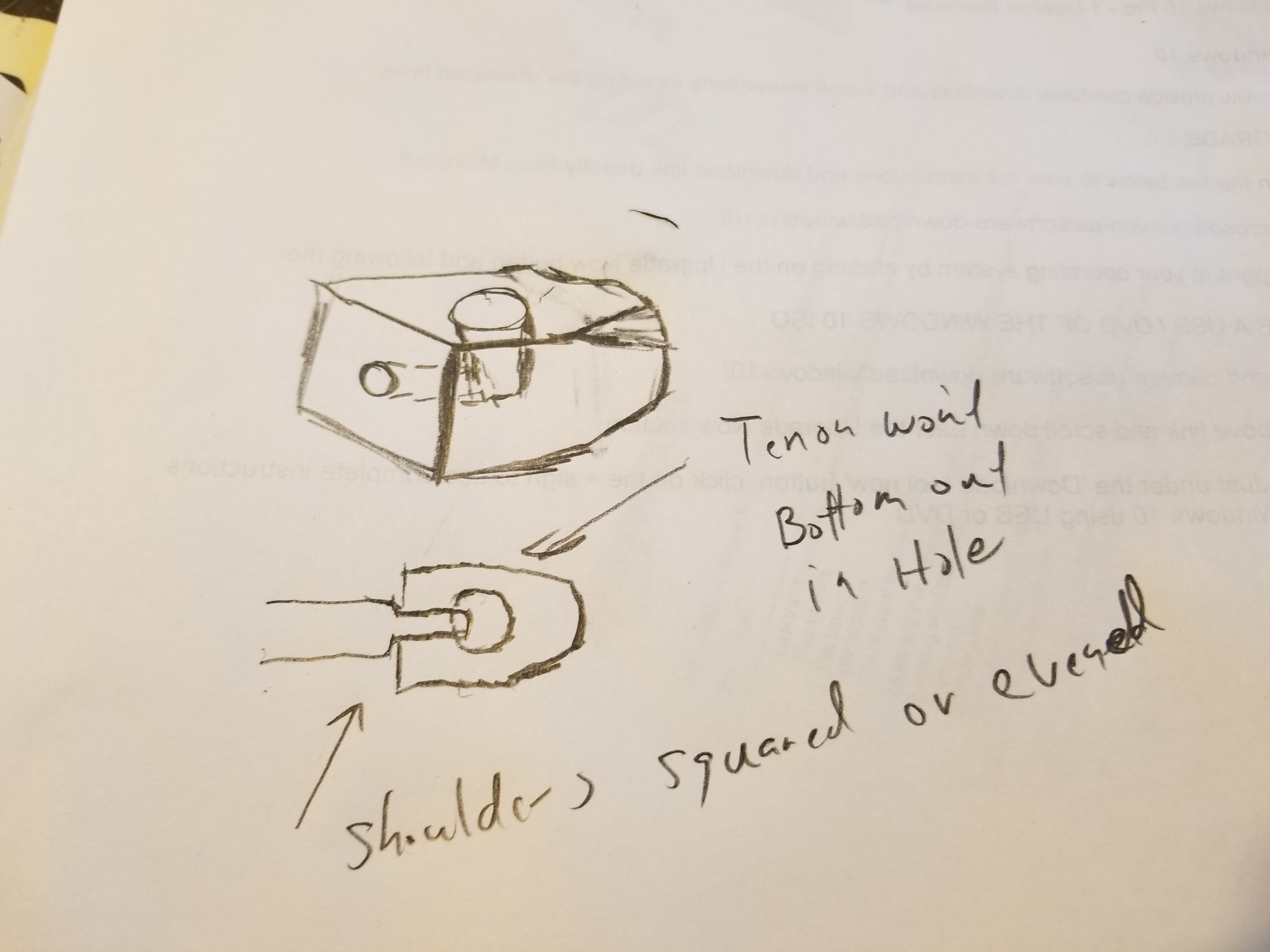
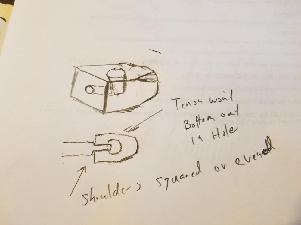
If you are making a real Monkey tool, you need a side hole to see where the tenon is... Nothing against you, but I think a lot of people misunderstand what a monkey tool is actually used for.. It was used to square the shoulder on a mortise and tenon assembly like wrought iron work and such and was struck on the end against the bar.. IE the monkey took was struck with a hammer. A bolster plate was used for general shoulder work and the metal being work was struck against the plate, much like a conventional heading tool but had different shaped holes and then a good old header.. Traditional monkey tool
-
A set tool is typically flat faced with a square faced edge.. But, they also made them with radius edges as well.. It was typically used with a bottom set.. I radius the off sides so I could use it as a multi set.. If the radius of the face is large enough it would actually move into the realm of fuller.. A set tool is designed to make a flat face up to a square shoulder.. A very particular function.. Nice work.. for the feathers a spring swage would offer the best advantage..
-
The Buffalo Silent 200 series is my favorite.. That is a later model with stamped steel fan case.. this model has the cast gear case so it's not the newest which has both a stamped gear case and a stamped fan case.. I prefer the cast iron gear case myself.. The last models had everything in stamped steel and the case got a little smaller.. As to the Cannedy Otto blowers they are filled up to the oil level drain and are a dry blower.. One of the only completely oil sealed blowers produced from day 2 of production. the Gear case gets filled with a light oil up to the drain.. There is also a hole in the crank handle boss that gets a drop here and there.. I own 6 Buffalo silent 200s ranging from late 1800'd to about 1910 with 1 a later unit from around 1930.. They range in Model size from 12" with 14" being the most widely produced size.. They also produced a 16" model for 2 years and then it became a special order item at a premium price.. Right round this time frame they switched from a double roller radial bearing (Magneto bearing) to a setup more like a ring and pinion the the bearing only on one side of the spur gear.. I prefer the models with both sides of the spur gear with bearings.. The years of production of the Buffalo blowers is funny because what they used for a size reference is beyond me as there is not one measurment that means anything.. The 12" doesn't measure 12", the 14" has the same case and fan case as the 12" with a larger fan blade.. The 16" is huge in comparision but its really only like 14".. I also own a Cannedy Otto Western Chief which is one of the highest quality blowers made and again.. Does not leak oil.. Every other blower maker Champion, Buffalo, etc, etc. are all oil leakers.. I've been looking in a way to put oil seals into the buffalos to stop them from leaking.. Eventually I'll post my findings..
-
I had seen in several books.. one was industrial forgings and the other was on vintage forgings either a train shop or the like.. In each of them they had pictures of forges that were mounted on the ground with only a slight lip with a back wall maybe 6'X8' or more with back blast setups.. the forge itself was 6-8ft or more in widthXlength.. Basically same setup as you had mentioned.. They also had centrally located work platform and from what remember in the pictures were basically a round wagon wheel affair with a center forging location with forges surrounding this area in a circular pattern.. Later on I had seen a video on Anchor making where it became apparent why the setup this way.. I'd be guess as to my assumptions but in the video it showed the Main forging as they added stock to it to gain in bulk and once the main body was up to welding temperature,, and the forge welding started they would walk up with bars at welding temp and they would be welded on, one after the other without adding back to the forge for a new welding temp.. Adding the bars in rapid succession kept it at welding temperature and was amazing to see.. Anyhow, it's all pretty neat.. Be great if there was more early movie footage of such mundane acts..
-
@eseemann NO.. I'm not Mr Charles.. but the simple answer is no.. You have to look at how steel moves or doesn't move (flexes).. There Is more mass in a linear function at the end of the rail if looking at the cross section ( T ) verses the side.. Go look at a power hammer.. Or as a great example a Spencer tire hammer.. These are all mounted standing up verses flat as you get the most resistance this way.. This not only applies to anvils, but splitting blocks or stumps etc, etc.. If you want an easy example go out and take a small sapling about 2 ft long.. Hold it in one hand at the top and put the bottom against your boot on the ground.. Now push on the middle of it.. It will flex easily.. If it took a set straighten it.. Now with it straight up and down.. Just push on the very end of it.. It will resist your pressure much better now.. Steel has a lot of flex to it just not as much as wood..
-
He's not saying it sucks.. He is saying there is a better way to mount it so it is more effective.. Please try to remember there are a lot of people here who have been there and done that on their way to finding a better way with less energy... Standing that rail on end, and welding on a larger diameter for the horn if really needed..