beaudry
-
Posts
188 -
Joined
-
Last visited
Content Type
Profiles
Forums
Articles
Gallery
Downloads
Events
Everything posted by beaudry
-
Manipulating a big hammer, installation
beaudry replied to Jspool's topic in Power Hammers, Treadle Hammers, Olivers
Nice looking hammer and a good size. It seems that another one of the unspoken benefits of a seperate foundation for a larger hammer is to physically isolate the operator from the constant vibration and impact transmitted through the floor. This cumulative effect of the constant impact transmitted up through your feet into your whole body can't be good for you in the long run and can really be wearing. I think the noise level in the whole shop must really go up with everything rattling with the transmitted vibration. My hammers are set on massive concrete foundation blocks below grade in my dirt floored forge shop so I'm protected from that transmitted impact, so I'm wondering if anyone that runs a hammer for any length of time on a monolithic concrete floor has noticed this effect ? -
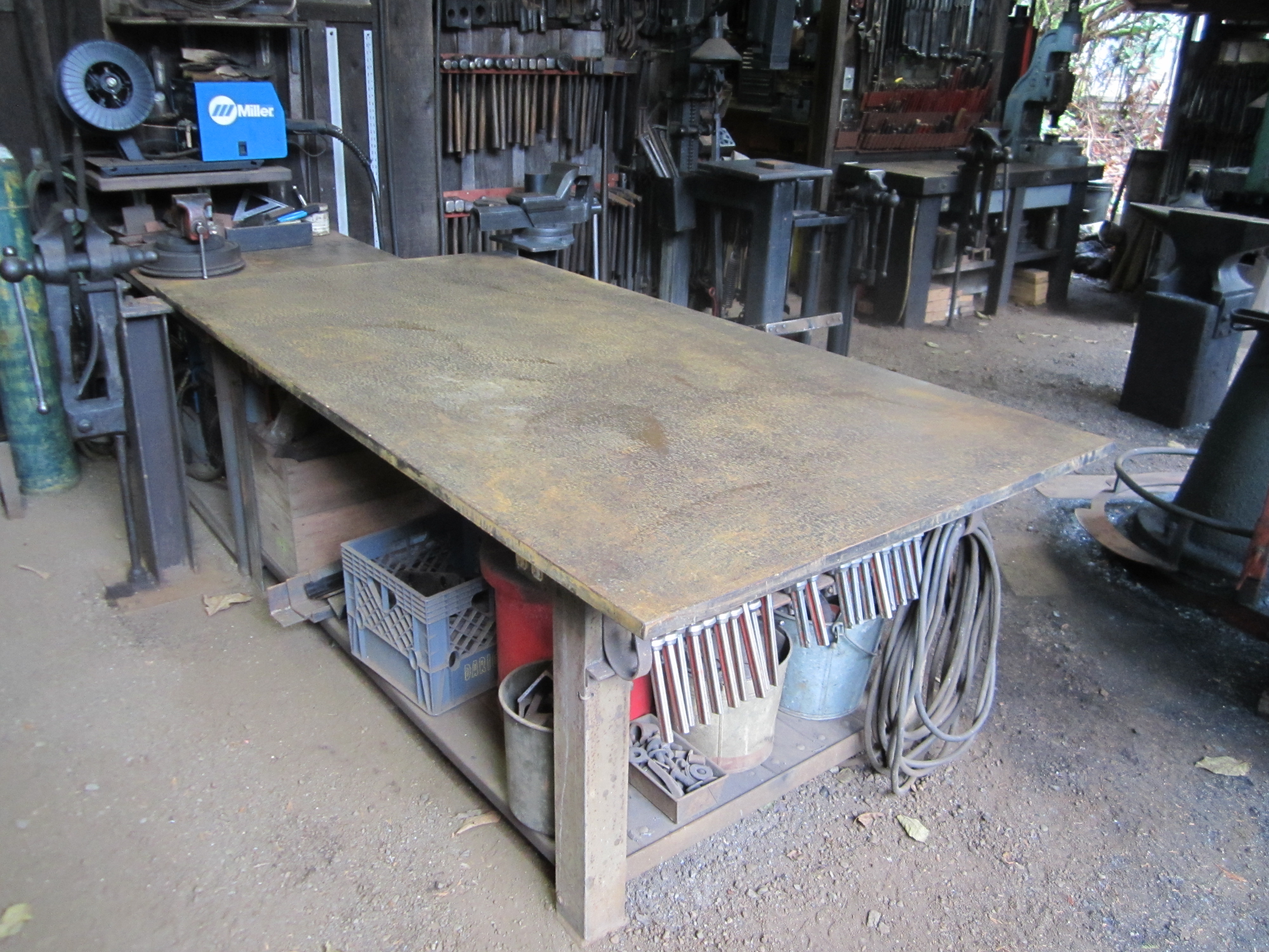
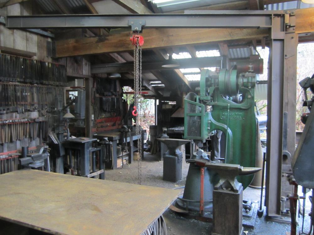
You could get by for a while with a heavy wood top with a piece of thinner plate on top. The main thing is that it is level and flat. If it isn't flat all your work ends up crooked or you are always having to compensate . Hold the legs back from the corners by the throat depth of your biggest clamps, so you can clamp fences ,stops or the work all around the edges and the corners of the work surface. A slight coating of rust on the surface holds a chalked line better than smooth plate and with care, a drawing in soapstone laid out accurately on the tabletop will last the life of the project. The red machine in the background in the second photo is a Cleveland 50 ton hydraulic ironworker. This is really handy for cutting bar stock and flats up to 10'' wide to length, and punching large holes , shaped holes and slots . The coper/notcher station gets used for profiling plate and mitering and notching angle iron and flats. Being able to do all these kinds of operations by shearing action is so much faster and less painful than drilling or sawing. The hole punch and dies will probably punch up to a thousand holes if not abused . There's another steel table with a vise behind it for catching cutoffs .
-
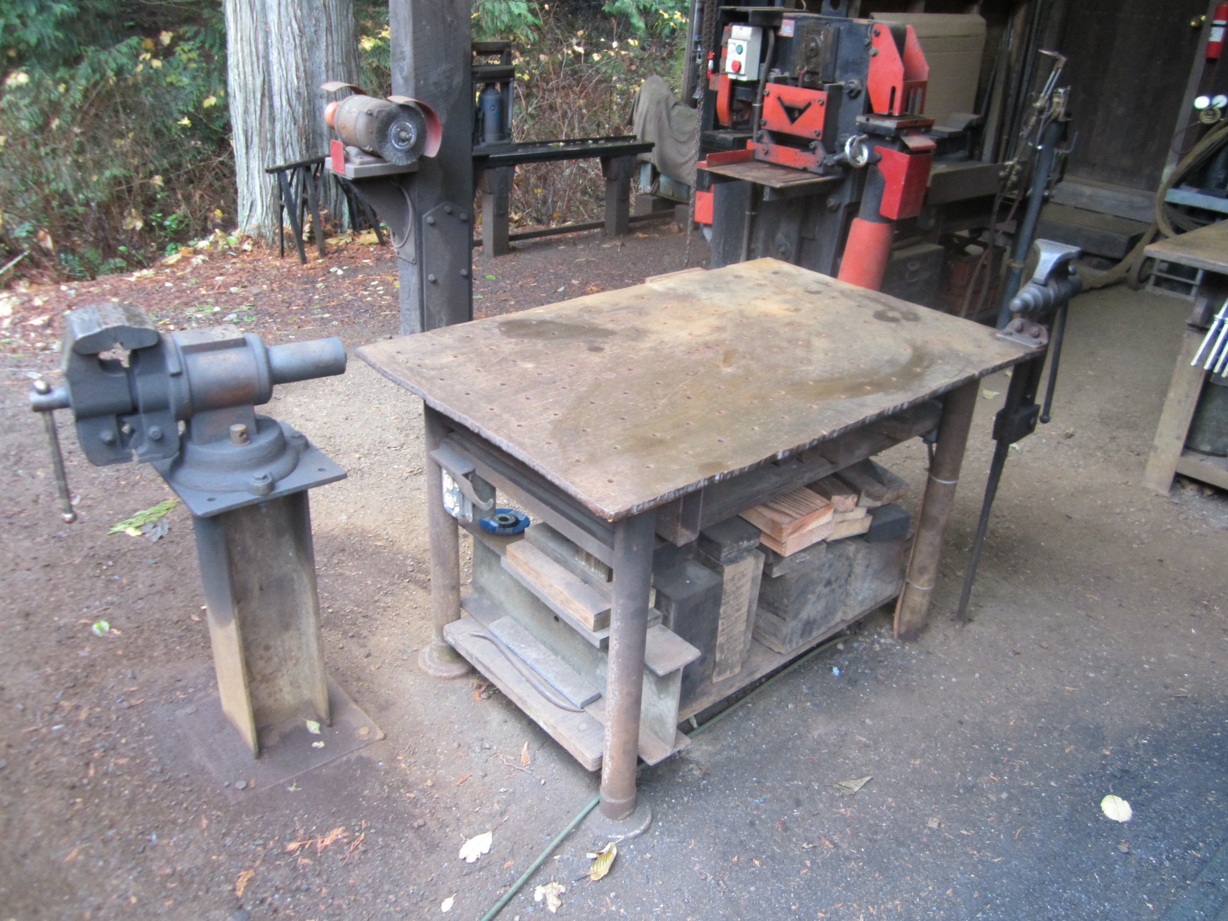
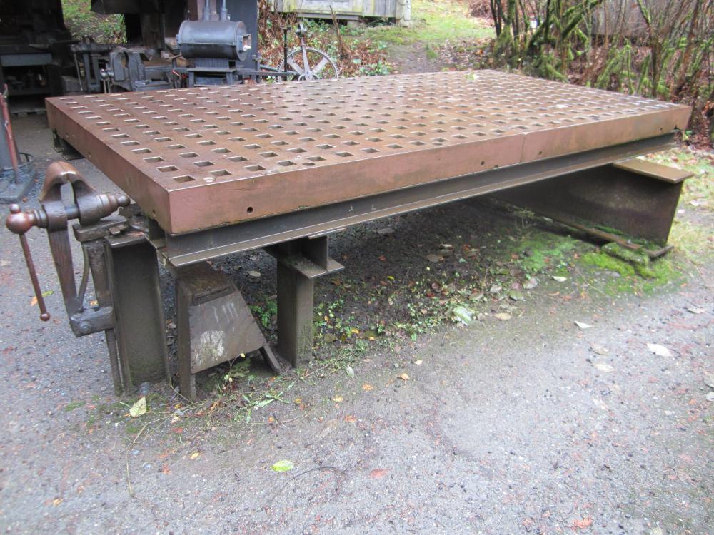
One of the most important ''tools '' that I have in my shop are my layout/ work tables. The main function is for laying out and assembling projects as they develop . They are heavy enough to straighten long bars , but I try to minimize the heavy pounding , using the anvils or heavy platten table for that purpose instead. These are carefully set up level with square corners so that they function as a quick and accurate reference point when forging or fabricating a part to shape. A finished length can be marked on the table with soapstone when drawing stock to size or a hole layout can be referenced or a bend or curve laid against a marked line. The table top is kept clear except for the job and tools at hand with a lower side table to keep parts or additional tools handy but out of the way. A heavy bottom shelf is handy for storing jigging materials as well as cross bars for hanging clamps. Having electrical outlets wired in near each corner keeps cord clutter to a minimum and there is a solid ground that is permanently mounted directly back to the welder. Fo large projects it's handy to have two tables set up level with each other with a gap between them to get access into the middle of a big assembly. It's handy to have a vise or two near the corners , but mounted off to the side on a separate post and footing so that the whole surface of the table and the edges and corners are kept clear. Good lights and the jib crane overhead complete the set up. Here are a couple in my shop; main layout table 82''x 42'' x 1'' plate, weighs about a ton, sits on concrete footings below grade. 36 '' x 48''x 5/8'' plate with grid work of bored and tapped holes. The cheap chinese rotating head vise is set low and is very handy for grinding , and cutting. Set same level as main table. Smaller tables with various post vises and flypress and next to the forges. These are a place to hold tooling or to do smaller layouts for parts being worked in the vise or press. 5' x 10' x 5'' platten table set up level on heavy foundation. The post vise is set so the jaws are below the table top so there is no obstruction for long work. The table top weighs about 5,600# and is bolted to the frame anchored into the foundation. There's about half a ton of various tools , clamps , dogs, bending pins ,etc, made to fit the 2'' square openings in the table.


-
Manipulating a big hammer, installation
beaudry replied to Jspool's topic in Power Hammers, Treadle Hammers, Olivers
While it's lifted up or lying on it's side do yourself a favor and trace the footprint and accurate centers of the bolt holes in the base on a piece of plywood. Mark the location and orientation of the dies on it and you can lay this on your floor and move it around to find the best and most useful spot for the hammer . A few inches either way or small difference in the angle of approach can make a big difference in how long of stock you can work etc. in the space you have. -
Manipulating a big hammer, installation
beaudry replied to Jspool's topic in Power Hammers, Treadle Hammers, Olivers
Mock up the profile with some sticks screwed together with drywall screws or a stiff piece of cardboard or plywood cut to size. Make it the size and shape of the hammer in it's biggest dimensions and see if you can get it through the door and standing up. This will tell you a lot right there and can help you avoid an expensive or dangerous mistake. It sounds tight. A couple of solid anchors in your slab might be handy . -
Show me your power hammer
beaudry replied to don't tread on me's topic in Power Hammers, Treadle Hammers, Olivers
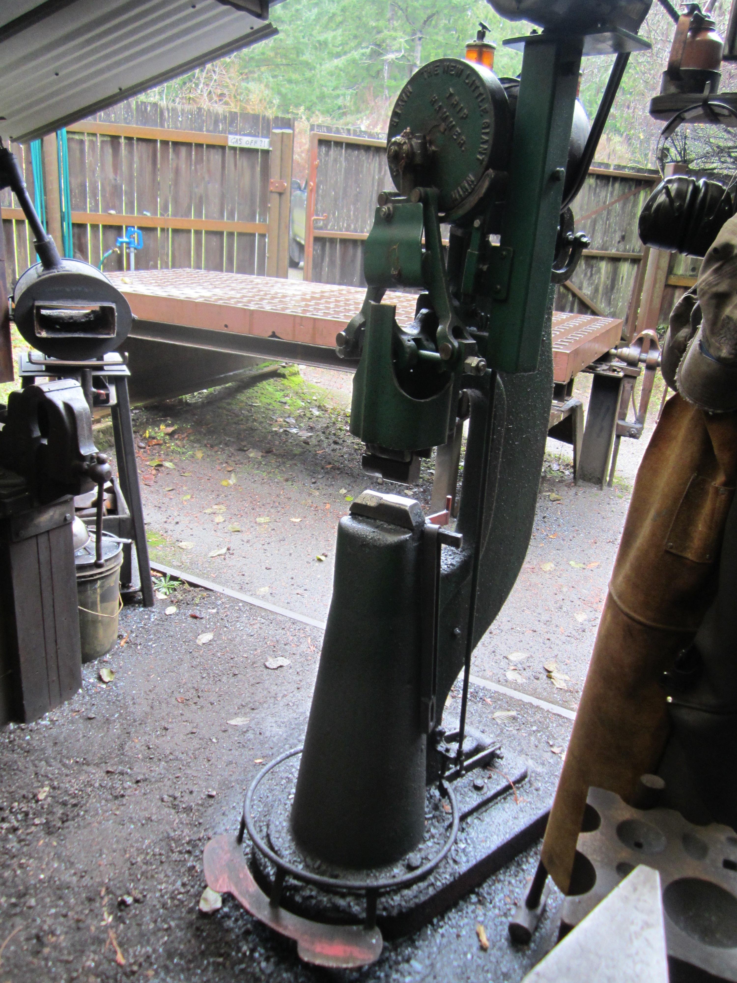
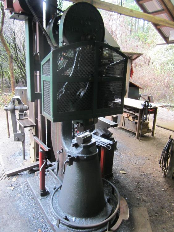
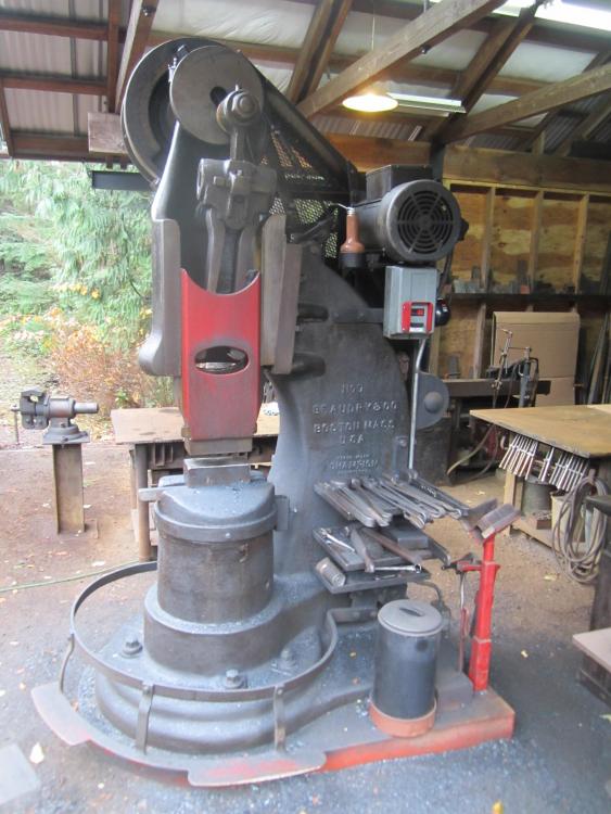
The arsenal from smallest to biggest; 1910 Old style 25# Mayers Brothers/ Little Giant with combination dies. Shop built motor mount , dropped treadle, brake and spring guard. 1922 Old style 100# Little Giant with drawing dies Shop built motor mount , wrap around guard, dropped treadle, tool holder , tool tray and over the top band brake 1924 [?] 200# Beaudry Champion #7 two piece motor driven hammer with flat dies and factory brake Shop built motor mount , jackshaft speed reduction , belt guard ,dropped treadle and tool tray and holder.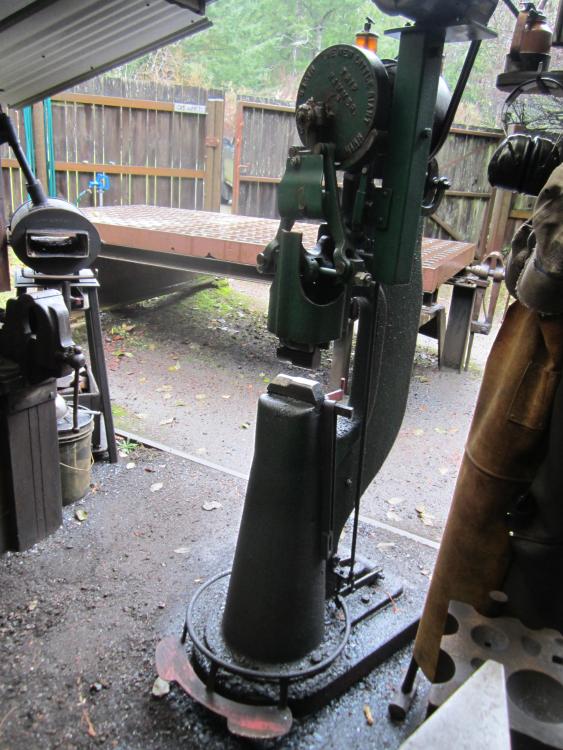
-
mayer bros power hammer spring issue
beaudry replied to bhixson's topic in Power Hammers, Treadle Hammers, Olivers
Thanks for the update. Now we all learned something. I've never seen a pitman like that before with it clamped around the crank plate pin. What year is this hammer ? I did a google image search last night and found all kinds of pictures of Mayer Brother - Little Giant hammers with vertical pitmans, hanging pitmans, ears up, and ears down on the crosshead. These are wonderfully simple machines , but everything needs to be compatible and adjusted properly and balanced to work right,. It's obvious that there are quite a number of different configurations and variations on the theme. -
mayer bros power hammer spring issue
beaudry replied to bhixson's topic in Power Hammers, Treadle Hammers, Olivers
The problem with trying to troubleshoot these old hammers, particularly Little Giants is that they went through lots of different variations over the years with different guide and ram set ups ,clutch location , length of toggle arms and methods of tensioning the spring as well as the orientation of the pitman and the crosshead on the crank plate. At this point in history, some of these machines are intact and original and others seem to be put together with cannibalized parts from other machines or rebuilt with varying rates of success by people with a mixed bag of knowledge and skills. My only experience is with the two LG hammers that I have , a 1910 25# and a 1922 100##, both old style hammers with the center clutch , wrap around guides and hanging pitmans and the crossheads ears pointing up. I bought these rebuilt as new from Sid at Little Giant 20+ years ago, because I wanted working hammers to make money with right away rather than spend endless amounts of time getting them up and running. I still suspect that your issue with it not hitting properly is how either the crosshead and/or the pitman is oriented. It's possible that you think you put it back together just as it was , but the fact that the crosshead is so far down or almost off the pitman seems to point to it being either way out of adjustment or put together wrong. Do you have a picture of the hammer from before it broke and was running properly ? Maybe someone that has experience with a hammer of that style and vintage will chime in and set us all straight. If you can get hold of ''The Little Giant Power Hammer'' by Richard Kern you might get some further insight into the mysteries your particular hammer, but it is by no means complete , long out of print and hard to find. Good luck ! -
mayer bros power hammer spring issue
beaudry replied to bhixson's topic in Power Hammers, Treadle Hammers, Olivers
Something doesn't sound right, especially if you have run this hammer with no issues and everything went back together exactly as it was before. Can you post a video of the hammer in action and a full on picture of the whole front end of the hammer? I think what you are calling the pitman arm is actually the Tbolt toggle links that make the flexible connection between the toggle arms and the ram. The pitman arm is what connects the crank plate [ heavy flywheel with the name cast in ] with the toggle arms through the crosshead. The spring is held in place between the bosses on the toggle arms by tension of the adjustment nuts on Tbolt toggle links The picture at the head of your original post shows the crosshead on the pitman to be hanging way down . Is that where it normally is set ? On second look , I'm guessing that the crosshead is actually installed upside down. I think the ears where the toggle arms are connected should be down rather than up. The height of crosshead on the pitman is usually raised or lowered by loosening the clamp bolt to adjust the height of the stroke of the hammer depending on the thickness of the material being worked. If the crosshead is inverted then the stroke can't be lengthened far enough to hit hard at the bottom Once the height of the crosshead is adjusted , then the spring tension is adjusted with the nuts on the Tbolt toggle links so that the links are level or pointing slightly up toward the ram at rest. The Tbolt toggle links on your hammer look like they are possibly too short as well. Try pulling the toggle arms off the links and and the crosshead off the pitman and reassembling it with the crosshead ears down, reverse the ends on the crosshead clamp bolt so you can tighten it up. Put the spring back in with your clamp and tighten up the tension on the spring with the nuts so that the arms are level or slightly up . Raise or lower the crosshead on the pitman until there is about an inch between the dies at full down at rest and see how it runs . You will be greasy and frustrated before you are done but hopefully you will have a smooth running hammer and learned something in the process. Keep us posted. -
I do get snow blowing into my shop on occasion but it's usually only a few inches. It's actually quite beautiful to be out there forging on a winters evening with snow on the floor. The climate here in the PNW is usually wet rather than cold so it's not bad working in an open air shop. I like the air circulation and the feeling of being outdoors all the time, while being protected from the very worst of the weather. It probably wouldn't work so well in a place like Vermont or Alaska It does always seem that during the very coldest weather , rather than doing nice hot forge work , the current project is at the stage doing the layout and cutting work on very cold steel . I looked at the available commercially built jib cranes and they seemed reasonable in cost, but not quite what I needed for reach and capacity for the existing layout and height of my shop. After I used it for a few years, I extended the reach of the boom on the crane in my main shop by cutting off the end and welding on another section of I beam. I have absolutely no worries about the strength of the arm , the weakest link is probably the chain and the half ton rating on the hoist.
-
My hammers have both a timber riser and a rubber /fiber conveyer belt pad between the hammer and the concrete foundation block. The foundation blocks are deep and massive, sized to fit the hammer and are separate from the rest of the floor. This is the method specified in the original factory literature for both Little Giant and Beaudry with long bolts connecting the frame and anvil of the hammer to the foundation. My copy of the Beaudry literature also calls out an alternative all timber foundation for the 300# hammer that is built up 4 feet deep of vertical oak timbers set on end and bolted to a larger timber ''floor'' at the bottom of the hole. It seems as if the point of having a heavy foundation under the hammer is to possibly increase the mass of the anvil as well as to support both the weight of the machine and absorb the and dissipate the impact of the blow then the cushion under the hammer would negate some of the advantages of such a massive and expensive foundation. The only reason that I've read to support having a slightly resilient cushion under the anvil of a power hammer is to give the anvil some ''spring '' under the impact . This would theoretically give a slightly longer lasting and more penetrating blow . Although the pad does help to even out any irregularities between the bottom of the hammer and the foundation, does anyone know the full reasoning for having a cushion under the hammer ?
-
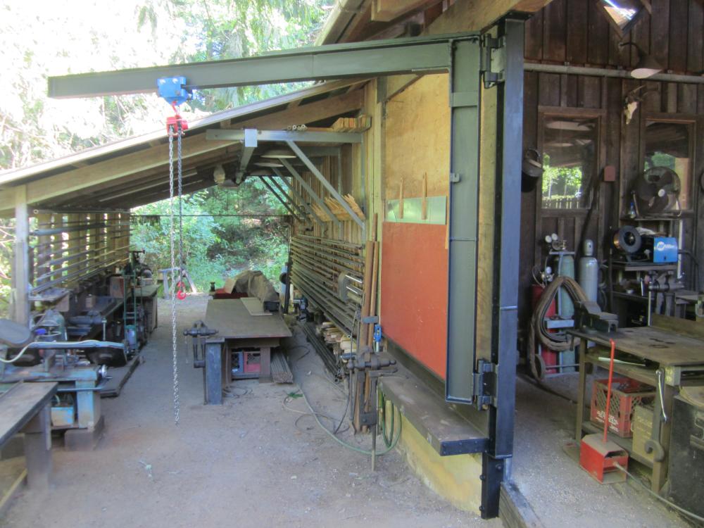
The advantage of a swinging jib crane is that it can reach all around and lift anywhere within its swing radius regardless of anything else in the shop . It's not a simple project to build one however and the building needs both a strong enough structure to support one and sufficient headroom for both the beam and the trolley and hoist. I do mostly large architectural commissions, like railings, stairs, wall panels and gates so this enables me to forge and fabricate and finish large projects and load them into my truck for delivery to a jobsite. Once there I can usually use the onsite crew and equipment to unload and get things into place for installation. This is probably far beyond the scale of most of the users on this forum, but is worth considering when designing or expanding a shop.
-
mayer bros power hammer spring issue
beaudry replied to bhixson's topic in Power Hammers, Treadle Hammers, Olivers
How about a length of threaded rod or a long bolt with nuts and some washers through the gap between the u shaped end of spring arms and the knuckle that holds the toggle arm. Or a pair of them through a couple of pieces of flat bar that spans the two arms. Use as big a rod as big as will fit in there for maximum pull. Maybe use the strap to get things started and to act as a preventer in case something comes loose A heavy duty welders bar clamp or possibly a pipe clamp might work too as long as it didn't slip. You can double nut it with two locking half nuts. These are made for that purpose and are about half the overall height of a regular hex nut. Tighten the first nut down to the proper place and run the second one down against and back the first nut off just enough to lock them together. You need two wrenches to do this. The tension on the arms should be such that the arms are level or pointing slightly uphill towards the ram at full down position at rest. Make a guard to go around the front of the hammer. Mock it up with some cardboard or plywood to get it right so you still have access to the adjustment nuts and lubrication points. Making the guard with some flat bar and 1/2' x 3/4'' expanded mesh will be solid enough so it doesn't rattle and will protect you from all those moving parts going around at face level and let you still keep an eye on things. You are lucky you weren't hurt when that spring came loose -
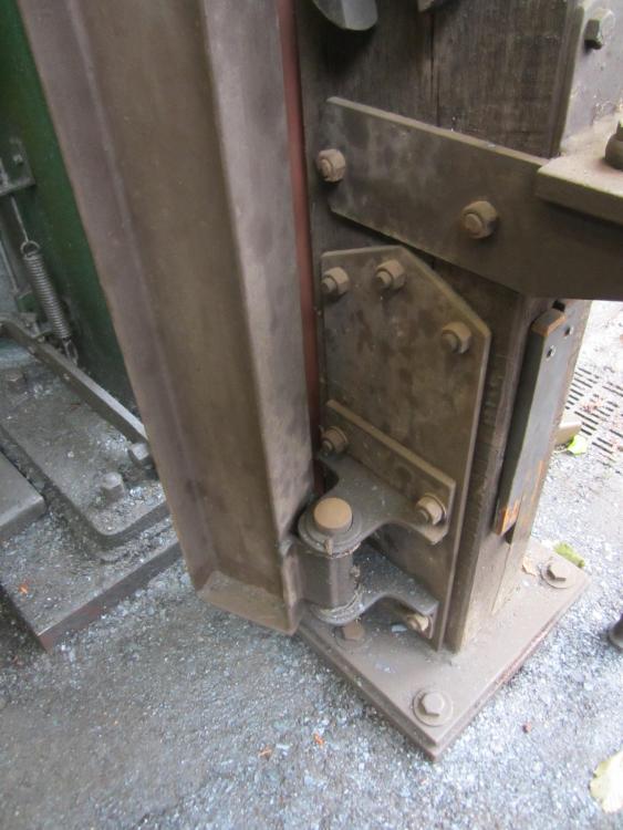
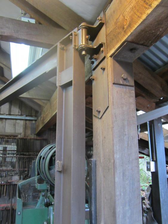
Here's a few shots of a couple of cranes I built in my shop to make it easier and safer to move big projects around. These are the jib crane design which give the most useful swing and reach with the least amount of space being taken up. There is a factor 3 pulling load at the top of the vertical leg with a correspondingly large thrust load at the bottom, so the building structure has to be built to take it. The pivots are oversized hinge barrel and pin bearings with grease fittings, easy to turn but with enough drag to keep things from swinging out of control. A crane would have been handy for installing these and welding the arm to the vertical leg in place, but careful planning and a temporary hoist got everything up and in position safely. All welding was done with a MIG that was powerful enough to do full deep penetration welds. The horizontal arms were welded with about a 1'' lift over the length of the beam to allow for any sag, but so far none has been detected , even under full load. With these two cranes I can move heavy completed projects all the way from the back assembly /finishing part of the shop into the back of my truck. A plate clamp and a selection of slings hooks and chains are handy for rigging . The beam trollies and chainfalls are rated for a minimum of 1,000 lbs. These aren't strong enough to pick up all but the smallest power hammer , but are really useful for handling the heavy parts when assembling and rebuilding the bigger machines. They have made a huge difference in the scale and size of the jobs that I can take on in the shop. Crane in main shop . Crane with swing from lower assembly area to upper level. There is an overhead track with a pair of trollies and hoist that runs the full length of this part of the shop . Bottom bearing and thrust plate Top bearing tied into header beam and roof truss.
-
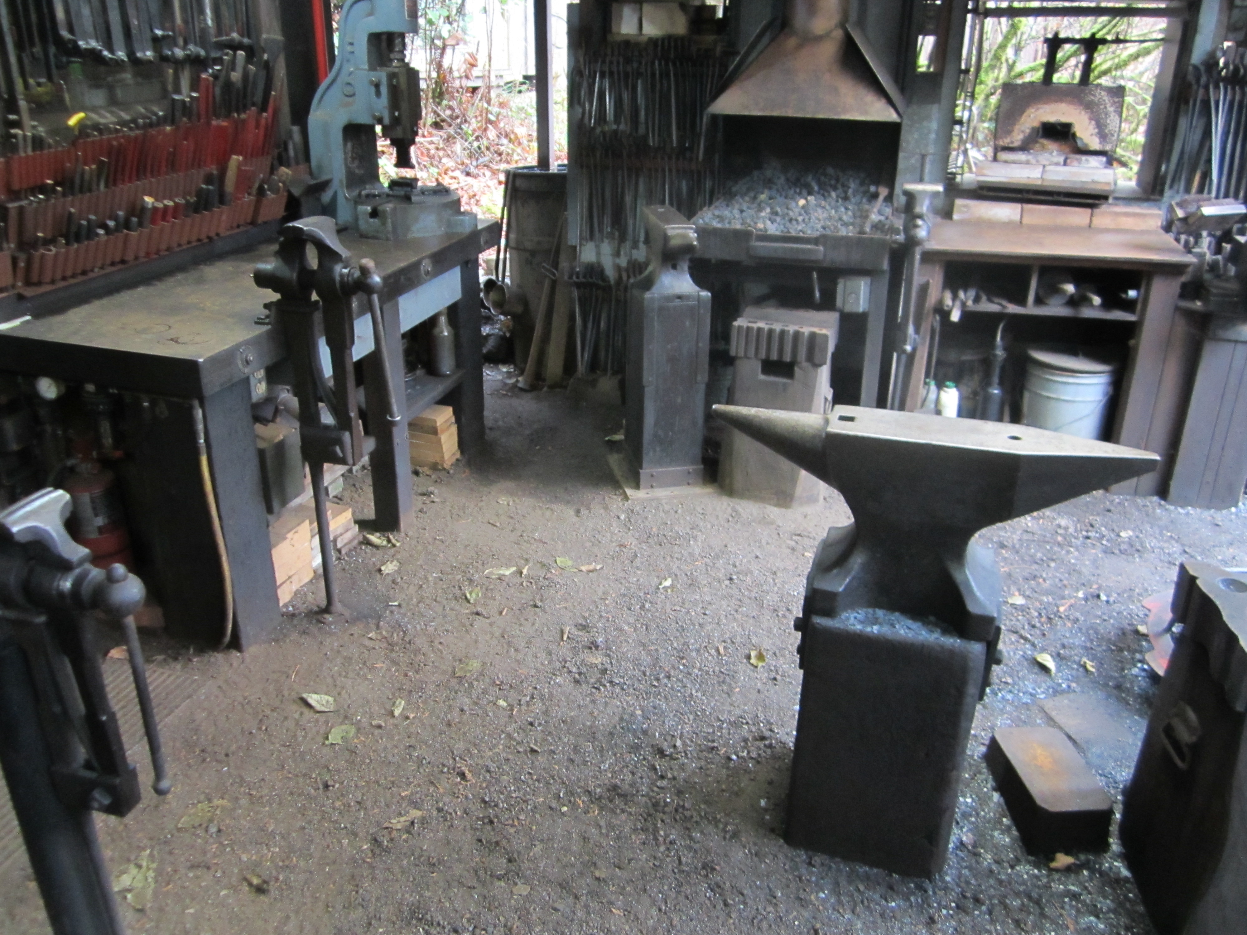
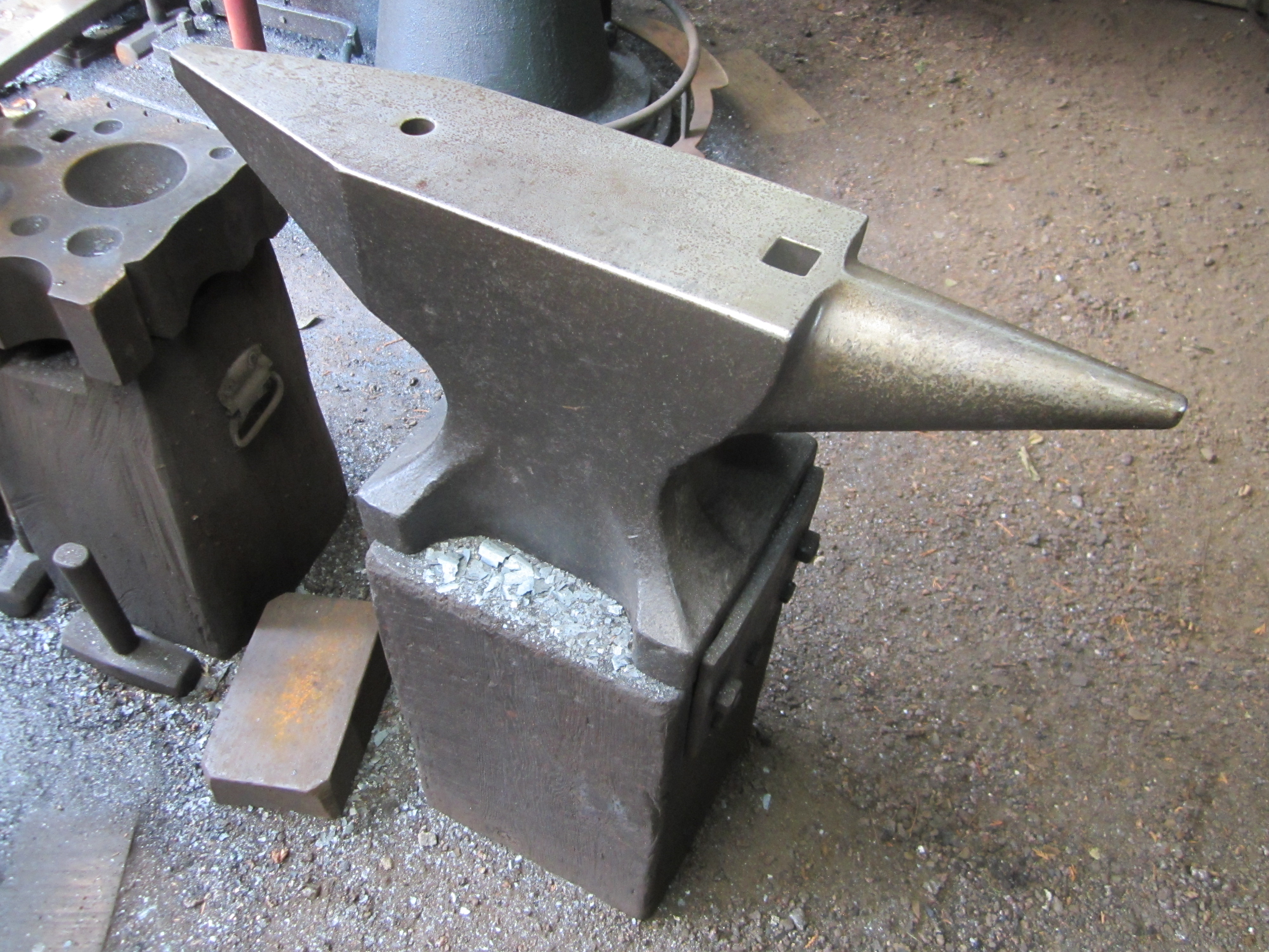
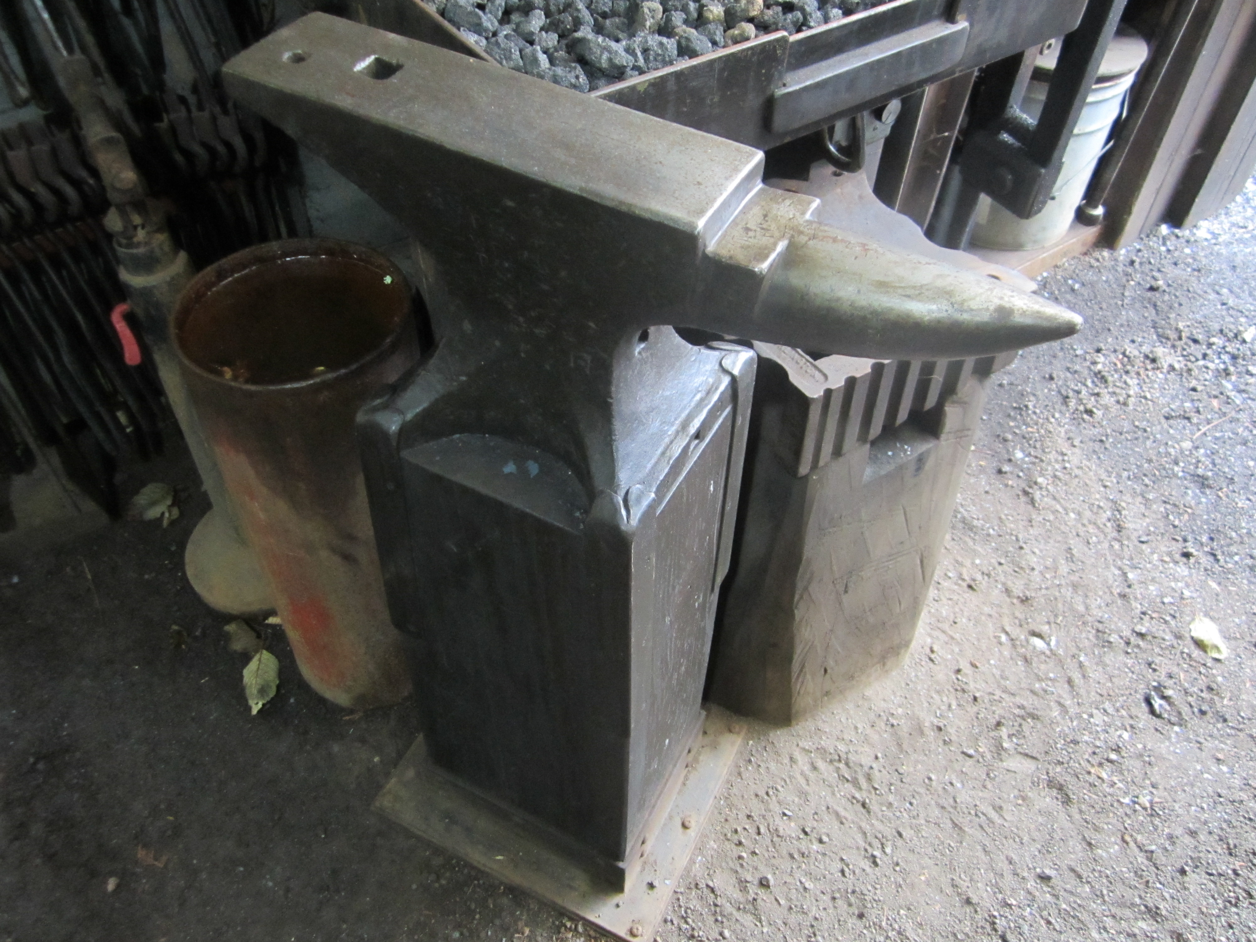
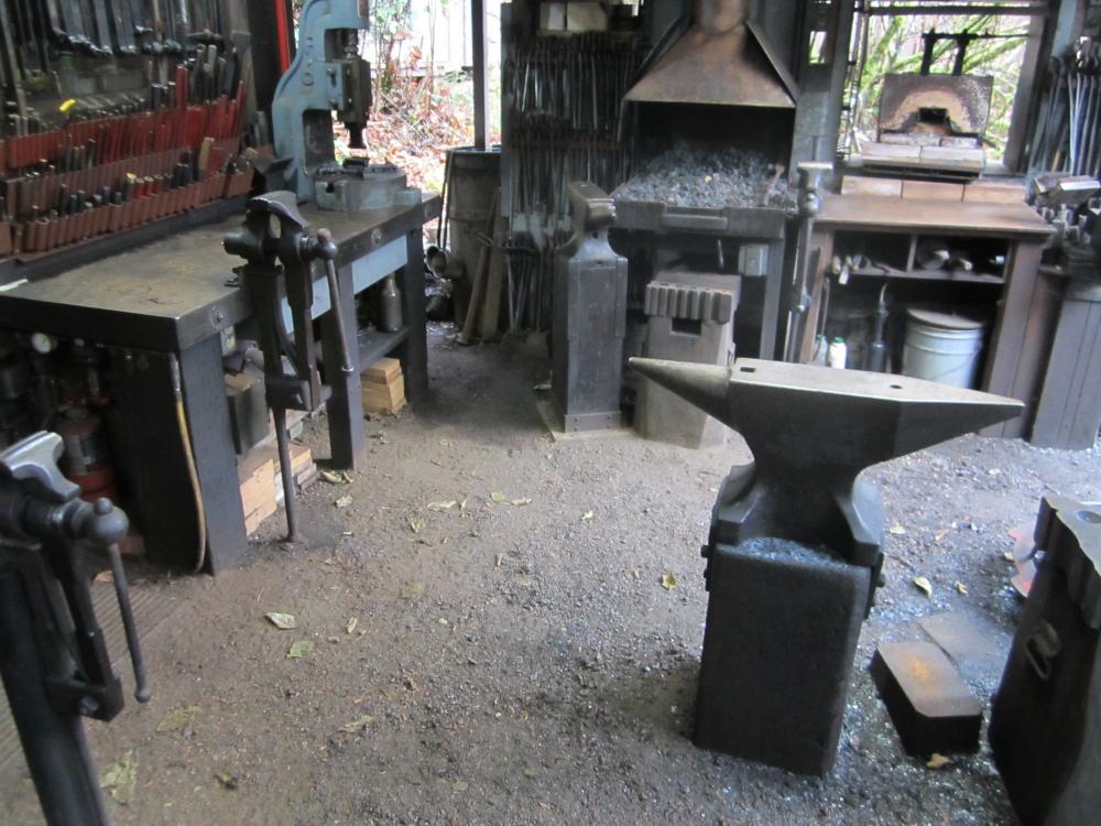
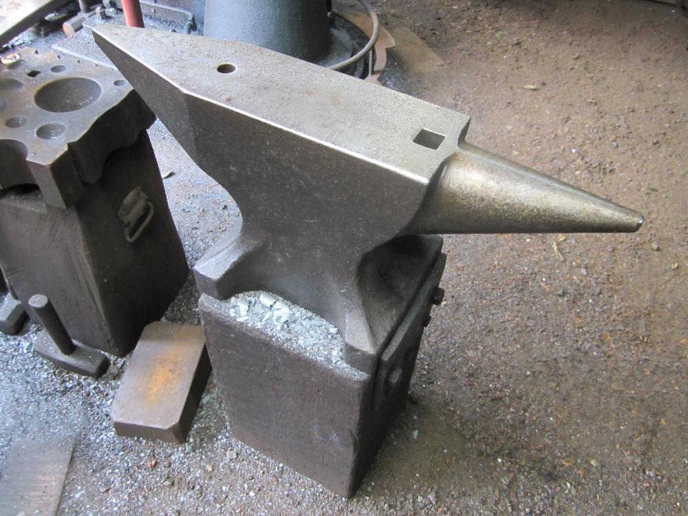
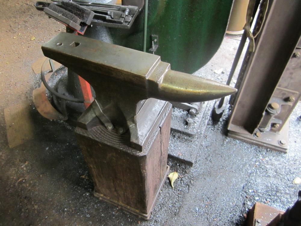
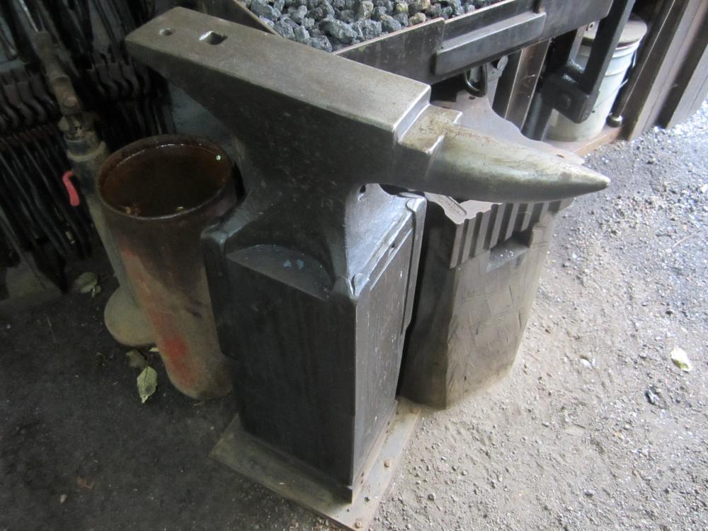
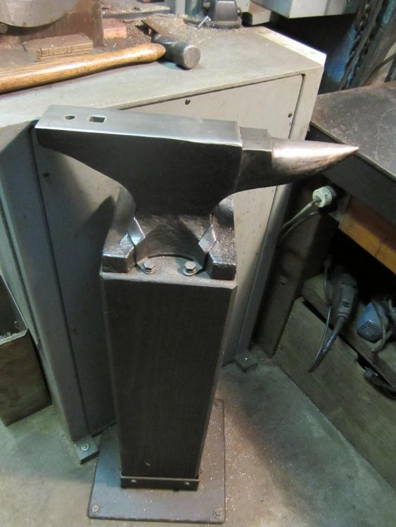
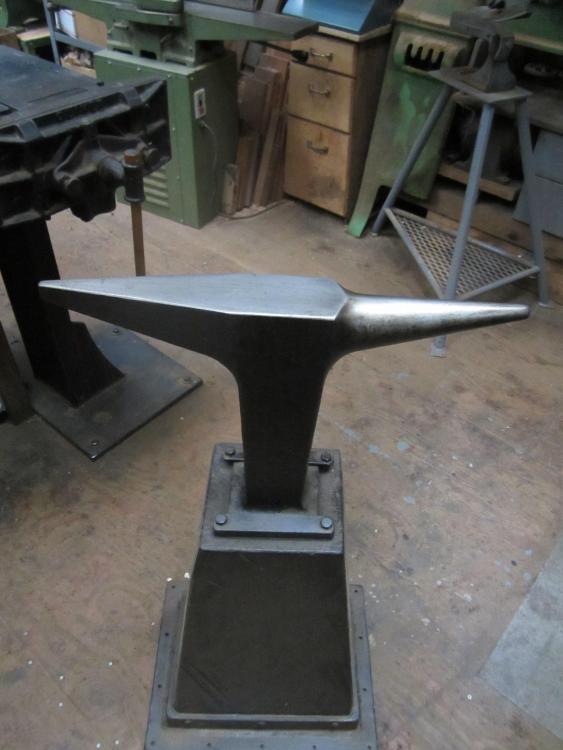
Main shop anvil. 260# Czech double horn. Block is set 2 feet in concrete below grade. Through bolted pinch plates hold anvil really tight and kills the ring. 50# sawyers anvil on floor for upsetting long bars 200# cast Swedish anvil. The anvil is held tight to block with forged straps . Block bolted into power hammer foundation . This anvil had several deep torch cuts when I got it. The cuts were welded up by a friend who is a certified industrial welder. I'm not sure what process he used but the repair is perfect and the anvil is very hard and rang like a bell before I strapped it down . The repair has held up with years of heavy use. This used to be my main shop anvil but is now mounted between the 100# hammer and my layout table. It mostly gets used for straightening or secondary operations after the work goes through the power hammer or for final tweeking during assembly on the table 140# Peter Wright. Held tight with fitted straps at corners of the feet. Block is bolted to concrete footing. This anvil is set higher than normal and is useful for small work close to the fire. 40# anvil , maybe a Hay Budden. Strapped down tight and base plate is lagged to concrete floor with lag shields. This solid mounting made all the difference in effectiveness for such a small anvil. This is mostly used for cold work in the machine shop. 60# Czech double horn stake anvil. This is the only one that is moveable but it can be screwed down to the shop floor if needed. This is mostly used for sheet metal work. The deep vertical mass under the center of the anvil makes this quite effective for it's weight
-
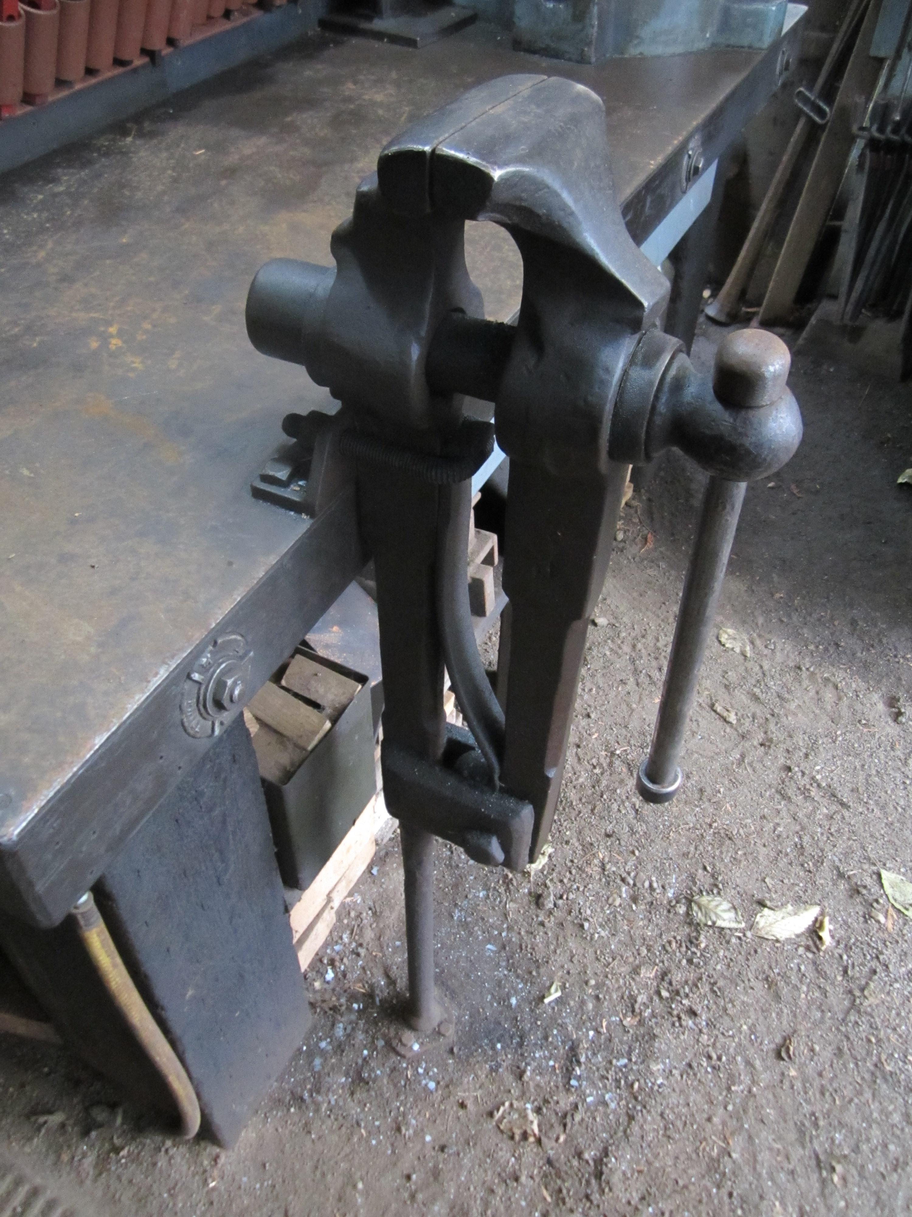
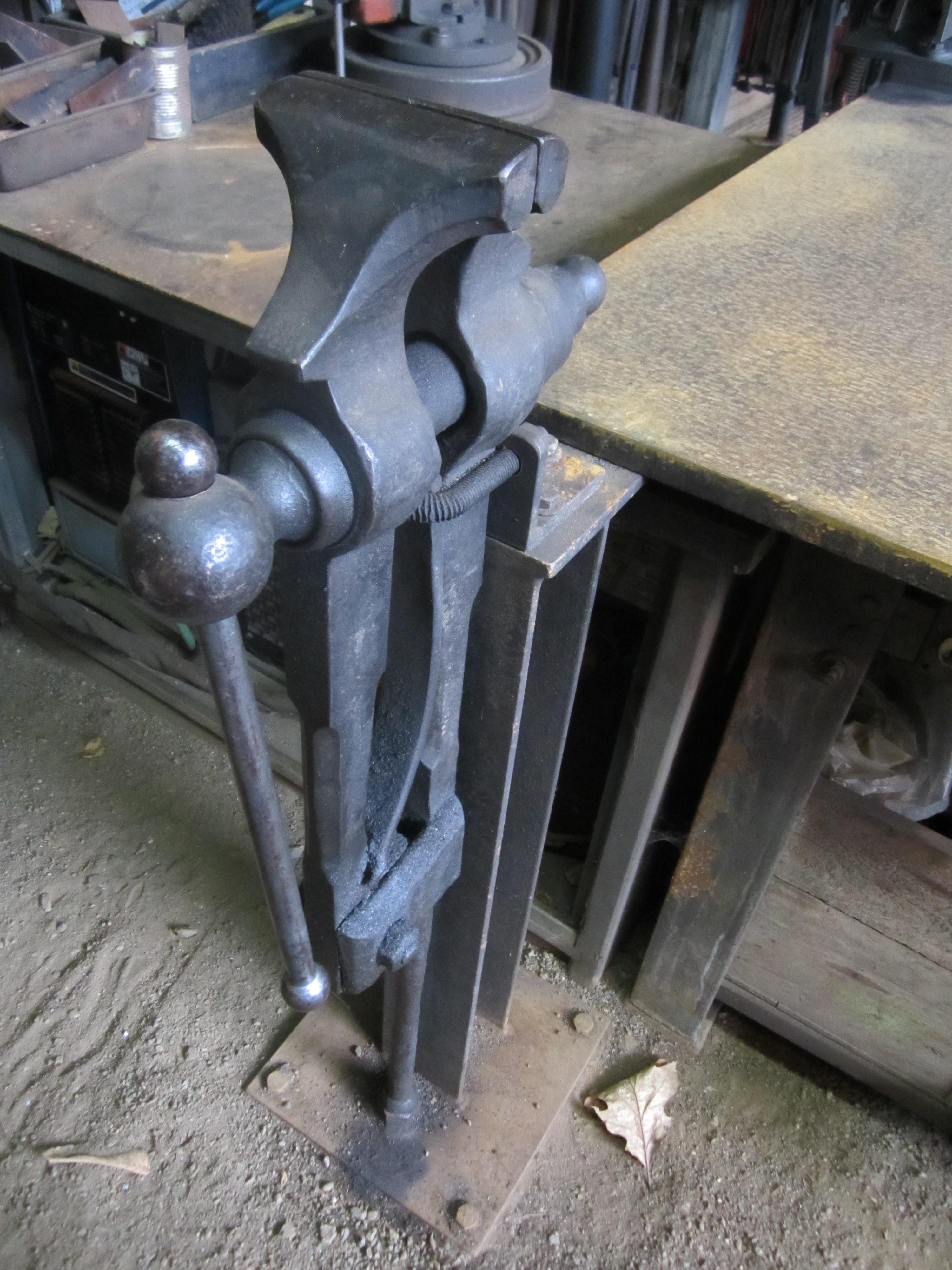
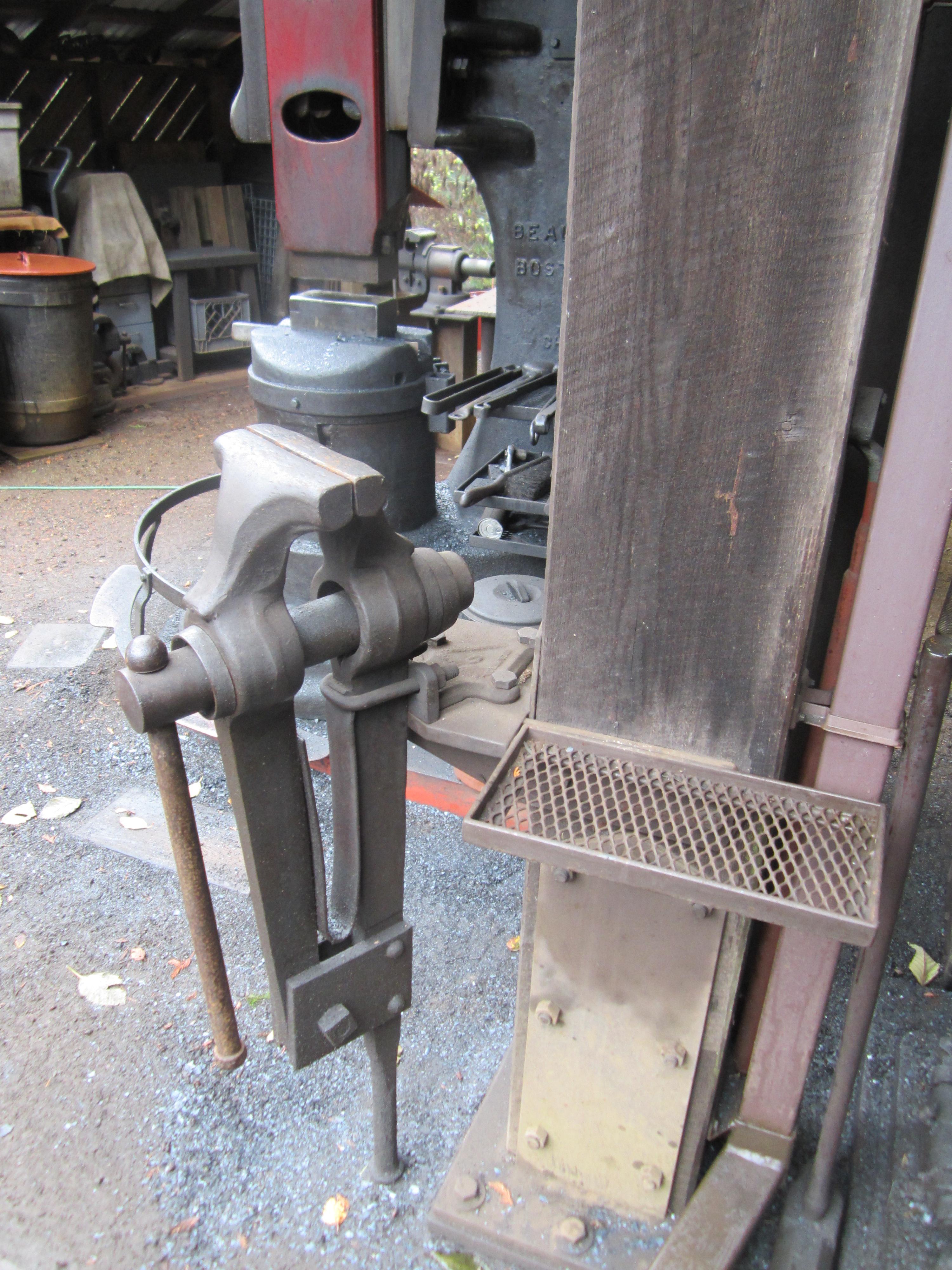
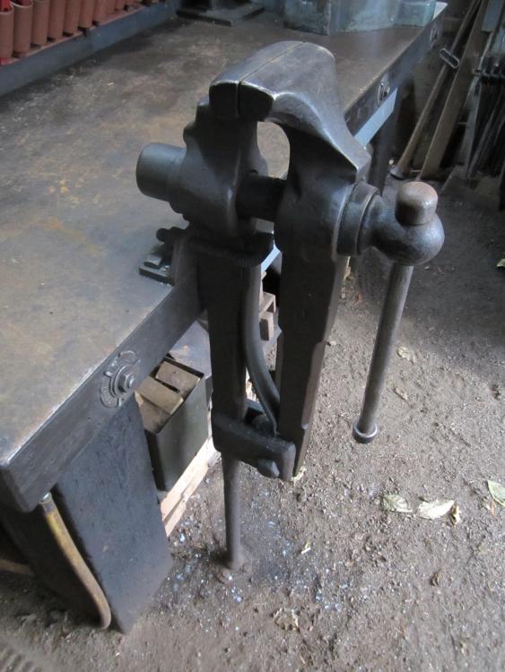
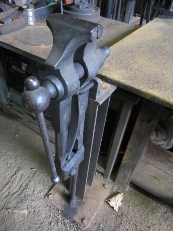
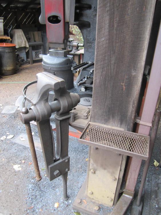
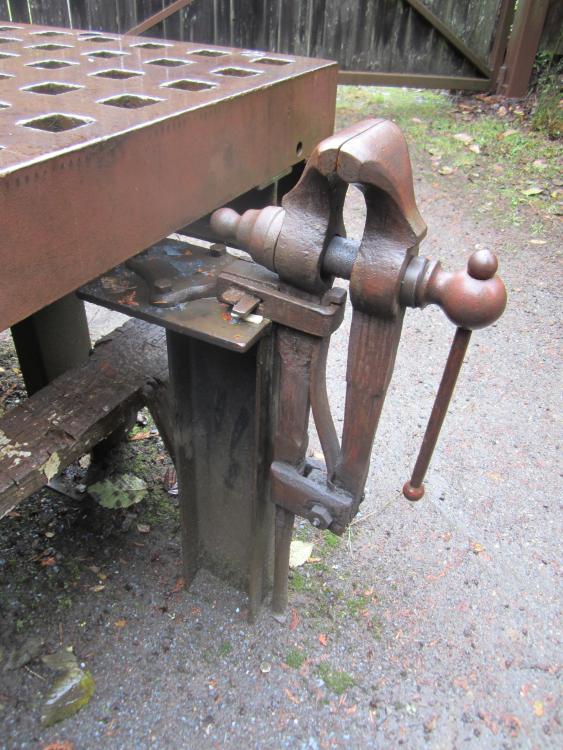
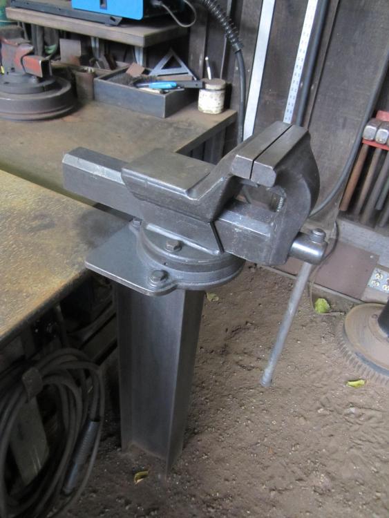
5 1/2'' Indian Chief. Bench legs and foot of vise are set in concrete and bench top is through bolted into wall . Mounted at corner of welding/ layout table on post bolted into concrete footing. Vise post bolted to underside of table. The vise is mounted so it does not take up any of the surface or edges of the table. 7'' Columbian mounted into main structural post and footing. The tool tray at right is handy for keeping hammers and tools handy for the job at hand. Vise mounted to steel post bolted to footing. Top of vise is below level of platten table , so no obstruction to long work on the table. Note grease fitting on leg pivot. Rigid 6'' machinist vise, on post at corner of welding table . This takes advantage of the mass of the table but doesn't intrude on any of the surface or edges of the table. These Rigid forged vises are the best new vises out there IMHO, more versatile and equal or surpassing the equivalent Wilton Bullets
-
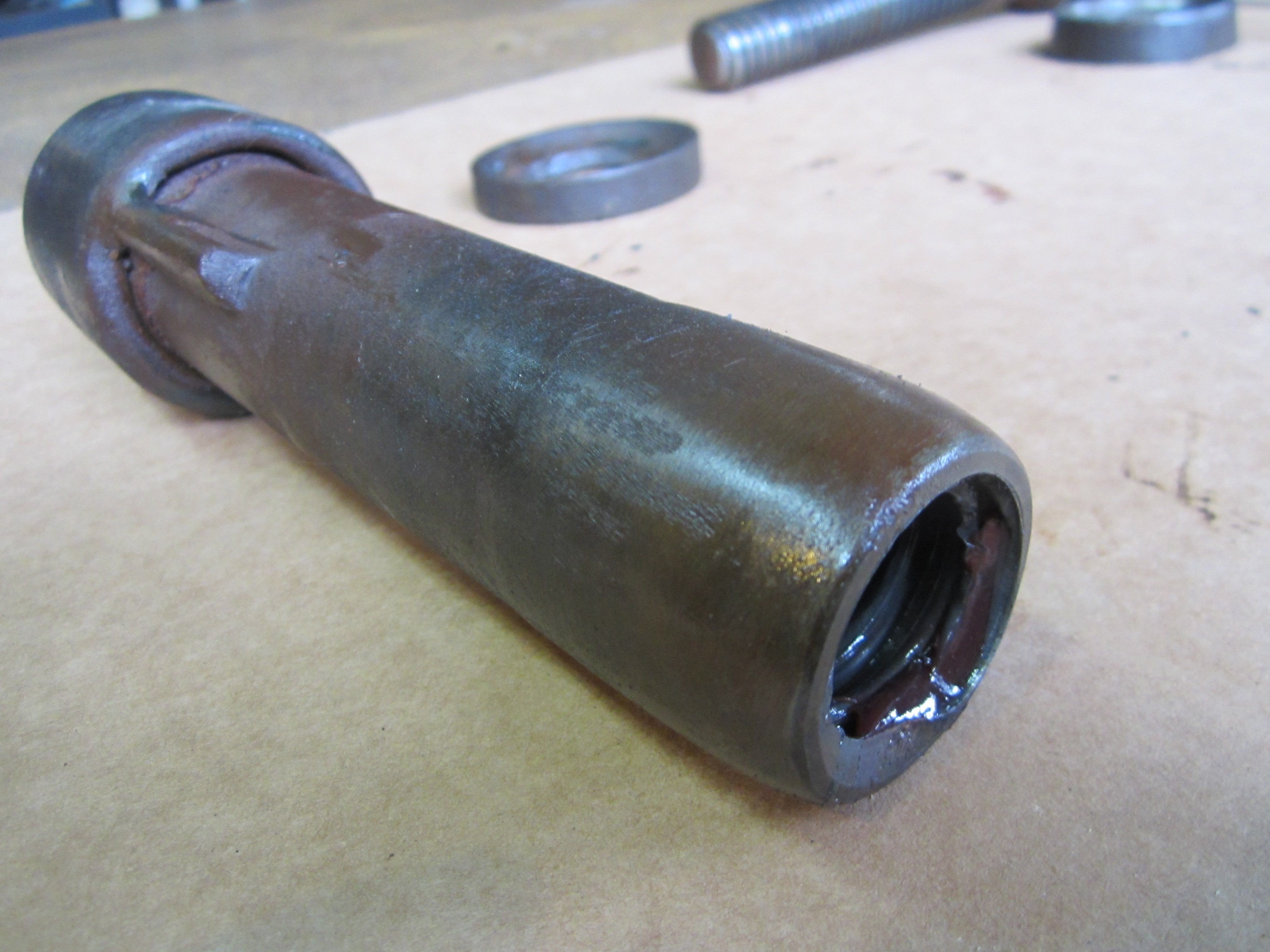
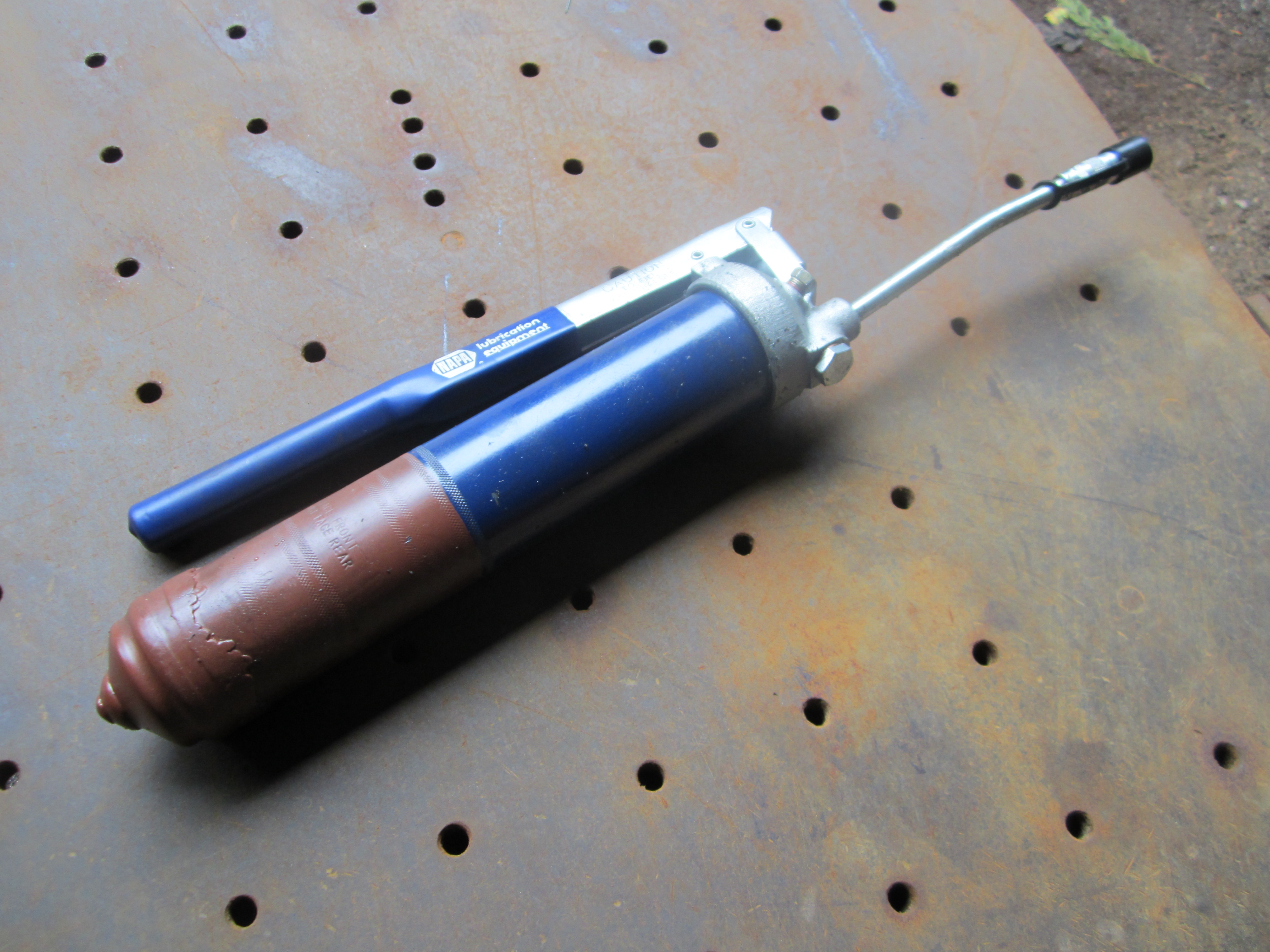
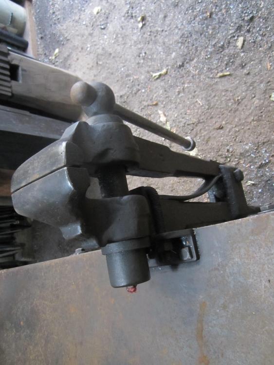
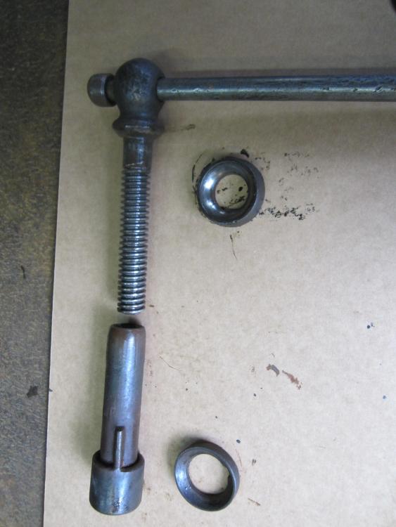
Vise and mount to bench. Back end of vise and screw box Replacement fabricated screw box and original spherical washers Acme nut welded to end of pipe section and turned / ground down to fit. Grease gun modified to pump heavy oil. Spring and push rod removed and hole plugged and bottom cap welded to body . Fill at the top at pipe plug with squeeze bottle with narrow spout.


-
Thanks , I'll take some pictures and try that.
-
I've been searching all over the forum on how to post photos , but haven't had any luck on how to do it. Can I just click and drag a photo from my Mac desktop and added it to a post ? Can someone help me out here ?
-
After 20 years or so, I completely wore out the screw in my most used vise , a 5 1/2'' Indian Chief. I bought a short length of 1 1/4'' B7 Acme threaded rod and a nut to fit it from Enco [ now MSC ] I fabricated a new screw box from an appropriately sized piece of heavy wall pipe with the nut pressed and welded in the front end. I welded a cap on the back of the crew box and bored and tapped it for a grease fitting. The screw box had a tab welded on so it doesn't turn in the back half of the vise. The screw box should be a somewhat loose fit in back jaw of the vise so it can pivot a bit to stay aligned as the vise opens and closes. The threaded rod was welded to the cut off stub of the worn out screw part of the handle. I ground everything smooth and gave it a black / rust patina with gun blueing to match the rest of the vise Lubing the vise through the grease fitting pushes the dirt and scale from the inside out. I use a grease gun modified to pump heavy way oil instead of grease which tends to hold dirt on the screw. This repaired vise has held up well in hard daily use and should give me at least another 20 years of service. As a side note, I use the same modified grease /oil gun to lubricate the clutch and main drive pulley on my No. 7 Beaudry / Champion motor driven hammer which has led to a dramatic improvement in the speed and control of that hammer.
-
How do you keep the vise post from wobbling in use even if it's a close fit into the tube ?
-
A good mount for a vise is a steel post [ I beam , square or rectangular tube or heavy pipe] welded to a 12'' x 12'' x 1/2'' base plate with a hole in each corner . Weld a piece of plate to the top to mount the vise to. Weld a short piece of pipe , coupling or a big nut as a receiver for the foot of the leg. Anchor the the stand to the floor with 1/2'' lag bolts screwed into lag shields [ if it's a concrete slab] drilled and set even with the floor. This allows you to remove the stand if you change your mind or need the room for something else. If you did an accurate layout with the holes in the base plate , you can rotate the plate so the vise faces various directions. Make a plywood pattern of the plate and bolt layout for future reference for interchangeable mounts for other tools as the need arises.
-
''I'm thinking a 1/2 steel plate big enough to give me good side to side and back and forth pulling without wanting to topple and a 6x6 post. And a couple raised casters to tilt and roll. '' If you want to get full useful value from a vise like this [or any vise ], skip the mobile stand and bolt the vise to a solid heavy bench anchored into the floor and/ or wall or to a heavy post sunk into the ground or bolted to the floor. Hammering, twisting and and reefing hard on a piece clamped in the vise is the daily diet of a tool like that and I've yet to see any kind of moveable stand that can really take it without moving. A lot of your energy goes to waste if every hit or pull makes it wobble, even a little bit. Same goes for an anvil. Just my 2 cents, based on a lot of years of experience.
-
My guess is maybe an older Columbian I'd skip the sandblasting and welding up the pits. Take a file or a sanding disc to any burrs or rough spots that keep anything from moving freely. This would be the area under the washer and the leg pivot point. The vise has a great patina from age and use, no need to try and make it look like new Clean the threads of the screw and the inside of the screw box with a toothbrush and some solvent. Oil everything up when you put it back together and keep it oiled in use. Nothing on that vise is cast, the bench mount plate was drop forged and may show a parting line that makes it look like a casting . Mount it to a solid post or bench and put it to work
-
Industrial Ajax Spring hammer HP?
beaudry replied to Krush's topic in Power Hammers, Treadle Hammers, Olivers
The stated horsepower of the motor seems to mean different things depending on the application. I have a heavy duty router thats rated 5 hp and fits in my hand. My 200# Beaudry Champion came with the original motor that was also rated at 5 hp and was 20'' in diameter and weighed 380 lbs. Can anyone explain the difference and how it relates to speed and torque and power output ?