beaudry
-
Posts
188 -
Joined
-
Last visited
Content Type
Profiles
Forums
Articles
Gallery
Downloads
Events
Everything posted by beaudry
-
Metabo and Fein for grinders , Tyrolet for hard discs, cut off and flapwheels.
-
Your toggle arms look short. With the spring at the proper tension the toggle arms should be level or pointing slightly uphill toward the ram when the hammer is full down at rest, not pointing down like yours are. A spring that is too long is going to make the problem worse , I think.
-
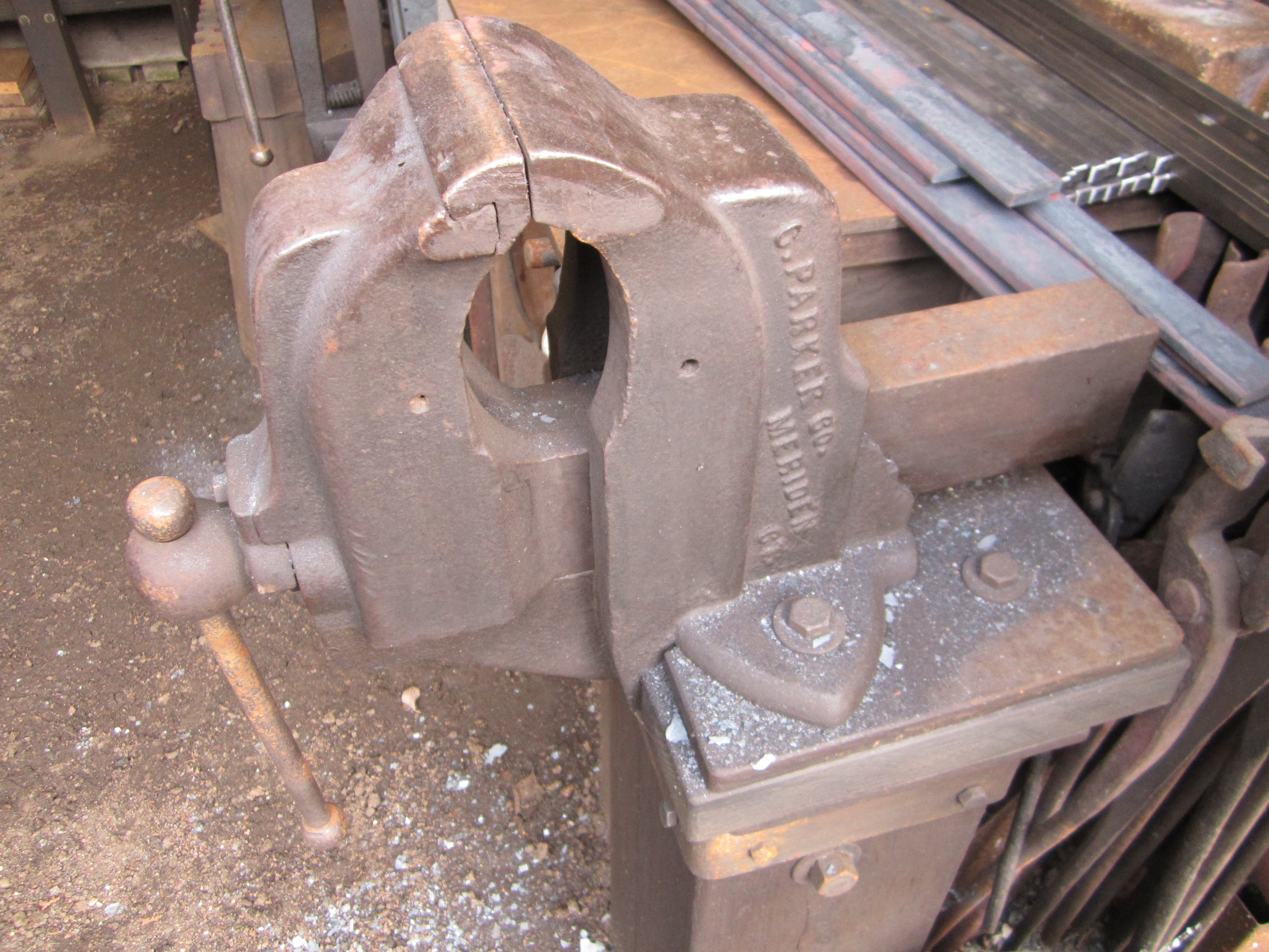
With the paint you can clearly see the parting lines on the front and back jaws/legs as well as the screw box ,so I would guess that it was drop forged . Maybe a Columbian but the screw box and mount suggest otherwise. Nice vise in any event.
-
A big heavy duty American made vise of comparable size and quality would run you close to $1,000 new. If you can use a vise that size and it checks out to work in other aspects it's a good deal.
-
I prefer to use a soft steel or bras hammer with some weight when striking a stamping tool . This seems to give a clearer impression, probably because it's more of a solid dead blow without any bounce or vibration.
-
Little giant issues
beaudry replied to Ranchmanben's topic in Power Hammers, Treadle Hammers, Olivers
When I got the hammer from Little Giant , they recommended the lighter oil on the clutch and something thicker like bar or way oil on everything else. The clutch is metal on metal . The only way to tension the spring on the old style hammers like mine [ built in 1922 ] is through the toggle arm bolts. The tension that seems to work best is where the arms are horizontal or slightly pointing up towards the ram at rest. Sid at Little Giant told me that in his experience the old style hammers with the center mounted clutch and wrap around guides hit noticeably harder and were easier to keep in adjustment than the new style with rear clutch and side ram guides. I can't verify that from experience, never having had the opportunity to use or really examine one of the new style hammers , but it seems there are some subtle but important difference in both how they are set up and how they perform. Since these hammers are all orphan machines, most of us are doing our best to keep the knowledge alive and get the best performance out of what we have. Why do you constantly waste our time having to edit out all the extra spaces you include here ? -
Little giant issues
beaudry replied to Ranchmanben's topic in Power Hammers, Treadle Hammers, Olivers
The washer that was put in to take up the end play of the main shaft is about 1/4'' thick and is between the back of the crank plate and the front top bearing. I put some oil on it when I lube the hammer before and during use. I think it also gets some of the oil that drips out of the front babbit bearing Please learn how to post -
Little giant issues
beaudry replied to Ranchmanben's topic in Power Hammers, Treadle Hammers, Olivers
The slop back to front in the shaft might be a factor in erratic performance. The clutch normally does't have to move very far to engage the spider. When mine was rebuilt they put a thick machined washer on the shaft behind the crank plate to take up the excess horizontal play in the shaft. The best thing about these hammers is that all the working parts are visible right out in the open where you can see what's going on. More editing of useless spaces -
Little giant issues
beaudry replied to Ranchmanben's topic in Power Hammers, Treadle Hammers, Olivers
My 100# is an old style with the wraparound guides and with the center clutch so it's set up a bit differently than yours. The clutch is all metal on metal. I've had problems with mine in the past with it getting cranky and not responding to the treadle after working perfectly all day. This seemed to happen most often when I was approaching the hammer from the left side , working across the length of the dies. I think I solved it by adding a second return spring on the left side of the frame to lift the treadle so the action was more consistent. I also put an additional spring pulling up on the clutch control arm where the treadle connecting rod meets it . I did this because the over the top band brake I made for the hammer is controlled via the treadle .The brake is disengaged through the same linkage that the clutch is engaged. I'll try to post some pictures of my set up tomorrow. These are good hammers and can do a lot of work, but everything has to be adjusted and balanced to work right. Are you getting any binding in your ram guides ? once again edited out useless spacings -
Little giant issues
beaudry replied to Ranchmanben's topic in Power Hammers, Treadle Hammers, Olivers
I run my 100# LG with 1 1/2'' between the dies with the ram full down at rest . This is where Sid at Little Giant suggested when I bought it rebuilt as new about 18 years ago. This gives a good hard solid blow at the bottom of the stroke and will work stock from 1/4'' up to about 2'' without adjustment. The tension on the toggle arm adjuster nuts should have the toggle arms level or pointing slightly up towards the ram at rest. Oil the clutch with something light like 30# thinned with kerosene or diesel. I think the fork popping off the tab on the clutch yoke would be a good thing to fix first Bend the fork in so it stays engaged and see if that helps Pictures would help placing each sentence on its own line is harder to read -
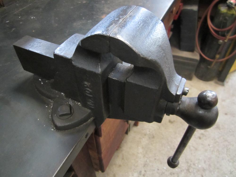
I have a couple of Parker vises, but neither are in good a shape as that one. The deep throat and relatively narrow jaws are handy for certain things. Great score ! What did you pay for that beauty ? # 88 1/2 with 4 3/4'' wide jaws. #102 with 3'' jaws

-
I'm not sure where you think a pipe section would be better for this style of crane ? All the commercially manufactured wall or post mounted jib cranes I looked at for inspiration were basically made like this . As it was ,It worked out that I could buy a full 20' length I beam cut to make both legs. The free standing cranes that rotate around their own post often use a large pipe section for the upright member. The trolley is made to run on an I beam section learn how to post please
-
You'll have to figure it out yourself for your situation and the expected swing and load requirements that suit your needs. You can mock it up with some sticks screwed together to figure out the most useful dimensions and location for your anticipated application. The only rule of thumb that I know of for a wall or post mounted jib crane like the one I built is that the pull load at the top and the thrust load at the bottom is three times the maximum load on the end of the horizontal beam of the crane. If in doubt , have it engineered for your application or buy a reputable manufactured unit with that already built in. Anchor it solidly .
-
It looks like the top and bottom dies aren't a matched pair in length and width . Is that intentional for a specific purpose or am I reading the picture wrong ?
-
If welding it doesn't work for some reason , an easy way to make a new one is to bend a piece of 1/2'' round rod into a ring the same size and weld it. Or you can drift out a heavy chain link to the same size if you happen to have one in your scrap pile. The washers on the outsides of the front and back jaws on most post vises is tapered like that on the inside to allow the thrust load on the washer to stay in line with the screw box as the tilts up and down slightly as the vise is opened and shut. The jaws of a post vise open in a slight arc as opposed to a straight line like a machinists vise, hence the need for some slight looseness in the screw and screw box in the body of the vise.
-
Time and some work will tell if it's stable enough for your use. I suspect it will need to be bolted down tight to the floor and maybe into a wall or post to get full use out of that vise. Having a table where you can put your tools close by handy . It looks like a nice vise. Columbian?
-
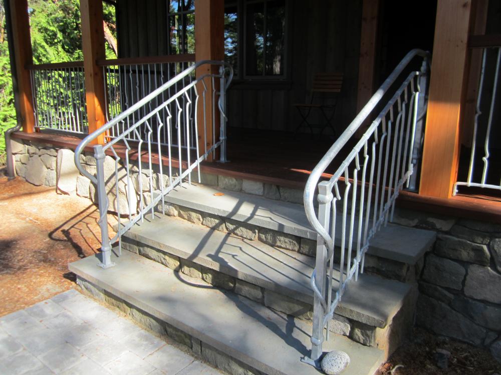
Thanks Joel , no worries on stating the obvious, better to have more information rather than less. I've done 50 or 60 large exterior pieces that were hot dipped galvanized over a forged steel substrate. These were all stair and balcony railings, mostly assembled in complete finished sections before dipping with traditional joinery like mortise and tenon, collars and wraps. Larger installations were assembled on site with galvanized or stainless steel fasteners. Bolt holes were all oversized by about 1/16''- 1/8'' to allow for the zinc coating The advantage of the hot dipping process is that it allows the molten liquid zinc to penetrate down into all the nooks and crannies , any place where water can penetrate and collect. Any hollow sections need to be vented with 1/4'' holes near each end . I was told that this is to allow stem to escape and if the operators don't think they are vented properly they will do it themselves with a cutting torch at locations that are convenient to them. I've also been warned that bar sections less than 1/2'' or so in diameter can get warped by the hot process. None of these pieces had moving parts that needed to both operate smoothly and be protected from rusting outside in the weather for years. My understanding of the zinc spraying that you are talking about is where a metal powder is shot through a torch flame by compressed air which deposits a thin layer of molten metal bonded tightly to the clean substrate. This seems basically like painting or powdercoating in that it is basically a straight line process and that the coverage is only as good as the dilligence and attention of the operator. It sounds as if you've been happy with the results and have had the chance to see how it holds up over time in a similar climate. I made some furniture components that were flame sprayed with bronze over steel. The thin bronze layer was sanded back in areas to highlight texture and then treated with a chemical patina and sealer. This was an expensive process but got the look the designer and client were after. edited more useless spaces
-
Thanks Joel for the tips based on your experience. I really ike the design and color of your gate . Did you just make the hinge pins and barrels extra loose and then file to final fit, hopefully leaving enough zinc in place to protect the steel ? I've found that if you request it ,the galvanizers will blow the piece of with compressed air when it comes out of the dip to minimize drips in the zinc coating. Any remaining lumps are best removed with a coarse rasp that doesn't seem to clog as easily as a file. Welds that you thought were ground and blended to be virtually invisible in the raw steel will stand out clearly through the finished zinc finish . editing more useless spaces
-
DuEulear , I made a similar table with the addition of a fan in the space below the cutting grate to suck out the vaporized metal dust coming out of the plasma cut as well as a door to reach in and pick up parts that drop between the bars. Anvil, I never intended to come across as saying that my way is ''the way'' , just being forthright about sharing some things that have worked for me over the years and for wide range of different projects. Maybe I'm too old school to really ''get'' emoticons. Of course I don't take down set ups for a specific job until I'm done with it . I do pick up tools or parts I'm not using if they are not needed or in the way, off to the side within reach if I'm going to be using them again soon or back to their usual place if not. The whole point of this thread was started by Glenn on ideas on how to set a useful layout / work table . I linked another thread that I had started about how a dedicated layout table was a valuable asset to a blacksmith shop. I included ideas and pictures of my shop set up and what I have found to be useful or not and why. You or anyone else are free to critique how my shop is set up, I do it myself regularly to see what I can do to improve the whole process. One or several, big or small , messy or neat a dedicated layout/ work table is a great addition to have .
-
Thanks Joel, that was just the kind of information I was looking for. I'll let you know how it goes. The thing I like about the hot dipping process is that it gets into all the hidden crevices from using traditional joinery techniques like collars . Does the manual zinc spraying process get in there as well ?
-
Just be glad your ''friend '' showed you where he was at before you had invested any more in the venture. There's no real reason you can't follow your dream of being a blacksmith yourself or need anyone else's permission to explore your passion. This craft is plenty hard enough as it is without letting someone else stand in the way with their xxxxxxxx The choice is up to you whether to cut the drama and get to work ..or not. editing foul language and useless spacing
-
They suggested that I paint the parts I wanted to stay ungalvanized with a thick coat of oil based paint. I was just wondering if anyone here had actually done it and what the results had been before I committed to the process.
-
I'm in the process of designing a large gate project and my preferred finish is to have the the two gates and two side panels hot dip galvanized for weatherproofing . I've had good luck with this kind of finish for forged exterior steelwork as the process gets into all the nooks and crannies and if it's done correctly doesn't obscure any more of the texture or detail than paint. The process is pretty cost effective and really gives superior weatherproofing in a wet outdoor environment. The main objection seems to be the silver gray industrial look but the zinc coating can be etched chemically or by a year in the weather before a color top coat is applied if desired. My question is how do I handle the parts like the hinge barrels and pins as well as the latch mechanism so that they either don't get coated in the process or the coating doesn't interfere with the action. The hinges will be an enclosed top barrel dropping down onto a vertical pin. The latch will be a simple swing latch operated from both sides. I've been told that the galvanized coating won't adhere to the steel without being etched and cleaned beforehand in an acid pickle bath. Should I paint or somehow treat the areas where the parts have to move so that they resist the pickle and the zinc coating or use stainless steel for those parts. Another option is to make everything a sloppy fit and then ream or file some of the zinc coating in those areas back to the desired tolerance before final assembly. Anybody have any real world experience with this and if so, what worked ?
-
They don't have to be auxiliary tables or benches to be useful. Shelves above and below bench height, tool racks on the wall , drawers or a rolling cart all provide ways to organize and store tools close by but out of the way so that whatever work surface you have doesn't just become a dumping ground and catchall. The whole point I was trying to make is that a dedicated and unobstructed layout and work surface is a a really [and in my mind vital ] useful addition to any kind of shop. Set it up to fit the scale of your work and the space available.
-
Interesting thread drift. Like I said, everyone is entitled to their own opinions and to their own personal methods to their madness. My experience and observation is that the people that are the most productive and the most efficient at actually making money at this keep things pretty well picked up and organized. How efficient is it to constantly have to move things out of the way of the task at hand or to be hunting around for a tool or part or short piece of stock ? My own preferred method is to take the last 10-15 minutes at the end of the work day to put everything back in it's place. On a large or complex project it can be quite a pile that's accumulated. When I start up again the next day, I know where everything is , so I'm not distracted looking through heaps of stuff or cleaning up before I can get going. But back on topic , I find that one method to combat clutter it's helpful to have side benches or auxilary tables close by as a place for all the tools and parts needed for the job without being in the way of the project underway on the main assembly/layout table.