beaudry
-
Posts
188 -
Joined
-
Last visited
Content Type
Profiles
Forums
Articles
Gallery
Downloads
Events
Everything posted by beaudry
-
^^^ I'm no engineer, but it looks that as long as those welds are good, that structure seems plenty stout to mount just about any kind of crane to.
-
^^^ If was going to do it again in MY shop, I would do it just like I did in my original post. Looking at all the factors involved in my shop set up , it was the best solution to give me the lifting capacity , height and reach for MY shop. I copied a proven commercially available design, bought good components and used heavy enough steel sections, welded it all with a powerful welder and mounted it to a solid building structure with an overabundance of heavy fasteners. There are a number of good designs out there, but they all have to address the load on the beam as well as the pull on the top of the mast and the corresponding thrust at the bottom. If the building structure that it is mounted to isn't up to the task , then it needs to be reinforced.
-
Some good designs here except the rendering of the one with just a pivot but no support for the arm either above or below. Having a diagonal strut coming down from above to support the beam simplifies the design, but loses some headroom. It seems the most useful design has the maximum height under the hook . The first design with the open frame diagonal brace with rom for the trolley and hoist to pass through is an ingenious solution .
-
Protective cover for bottom die
beaudry replied to beaudry's topic in Power Hammers, Treadle Hammers, Olivers
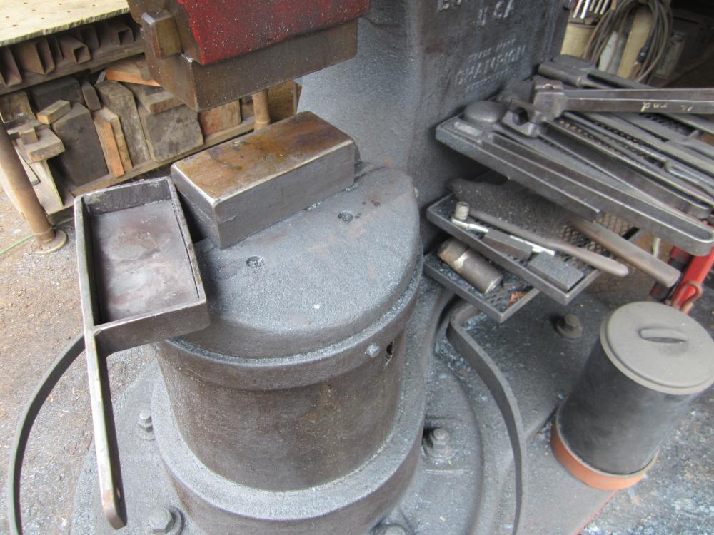
Andrew T, Other than the scale chewing up the dies they seem plenty hard and show very little wear after 12 years of use. The dies on my 100# Lg are also 4140 and seem to work just fine. I'd rather have them a little soft so I don't chip them. The flat dies have about a 3/16'' radius on all edges and are set to match top and bottom. The tool trays are handy to keep tooling close at hand .Accessories like belt dressing . the die cover and the wrenches to adjust the brake are on the lower tray. I mounted the trays using holes that were already drilled into the frame. There's about an 1/'8'' gap all around between the anvil block and the frame. I caulked it tight with some fiberglass furnace gasket to keep the scale out and from working down and under the anvil .I've read about people having problems with the anvil getting tilted with fine scale slowly working it's way under the anvil when it recoils under the hit. When I bought the hammer it was set up as a closed die hammer with big square dies with tapered notches for holding insert impression dies to forge star drills, punches and crowbar ends. The dies were really wedged in with the keys all smashed into a non removable mess. I cut the old dies out in chunks with a big OA cutting tip and lot's of pressure . I managed to do this tricky cut without any damage to the dovetails , I think helped by the slight gap in the key slot and the fact that the dies were higher carbon than the ram or sow block [?] It's been a very fine hammer , well mannered and very economical to run for it's size. -
over at garagejournel there's vise forum and some real vise nuts that post there. You might find out something there about your unique vise
-
Protective cover for bottom die
beaudry replied to beaudry's topic in Power Hammers, Treadle Hammers, Olivers
Leaving that argument aside, what are you making with a hammer that size, industrial forging or art work or a combination of both ? -
Best drill bits for 5160 steel.
beaudry replied to ZachNiedjalski's topic in Drills, Post drills, Mag drills, etc
I almost always use ''screw machine'' length drills rather than ''jobbers length'' because they are shorter and stiffer for the size. I usually use Hertel or better bits with the black oxide coating HSS to hold the coolant on the surface. I buy them in bulk from MSC. Sharpen them or toss them when they get dull. Lately I've become a big fan of a product called Syn Kool, a water diluted cutting oil that seems to work really well and does'nt leave such an oily mess to interfere with subsequent welding or finishing. Cheap bits and taps will end up costing you more than they are worth most of the time. -
Protective cover for bottom die
beaudry replied to beaudry's topic in Power Hammers, Treadle Hammers, Olivers
IW , thanks for the clarification, looks like a beautiful machine. I don't have enough experience running an air hammer to make any sort of valid comparisions. SI , The dies are 4140, not sure what the hardness # is. I can dress them with a new sharp file . I don't have the shop capacity to machine and heat treat a piece that size, so I had them made by Postville Blacksmith Shop in Wisconsin about 12 years ago. The swages I make are usually made from mild steel , left as forged. Most of my swages I bought from Off Center Tools, A lot of them came heavily pitted on the outside faces which I ground as smooth as possible. The damage I was getting is from the hard scale getting between the die and the swage. Having a piece of angle iron with two wire brushes mounted inside the angle fixed close to the hammer helps clean off the scale as well as having an air nozzle on hand to blow things clean. -
Protective cover for bottom die
beaudry replied to beaudry's topic in Power Hammers, Treadle Hammers, Olivers
Nice looking hammer, whats the ram weight on that ? What's a clear space hammer as opposed to a regular hammer? Got any side by side pictures ? -
Protective cover for bottom die
beaudry replied to beaudry's topic in Power Hammers, Treadle Hammers, Olivers
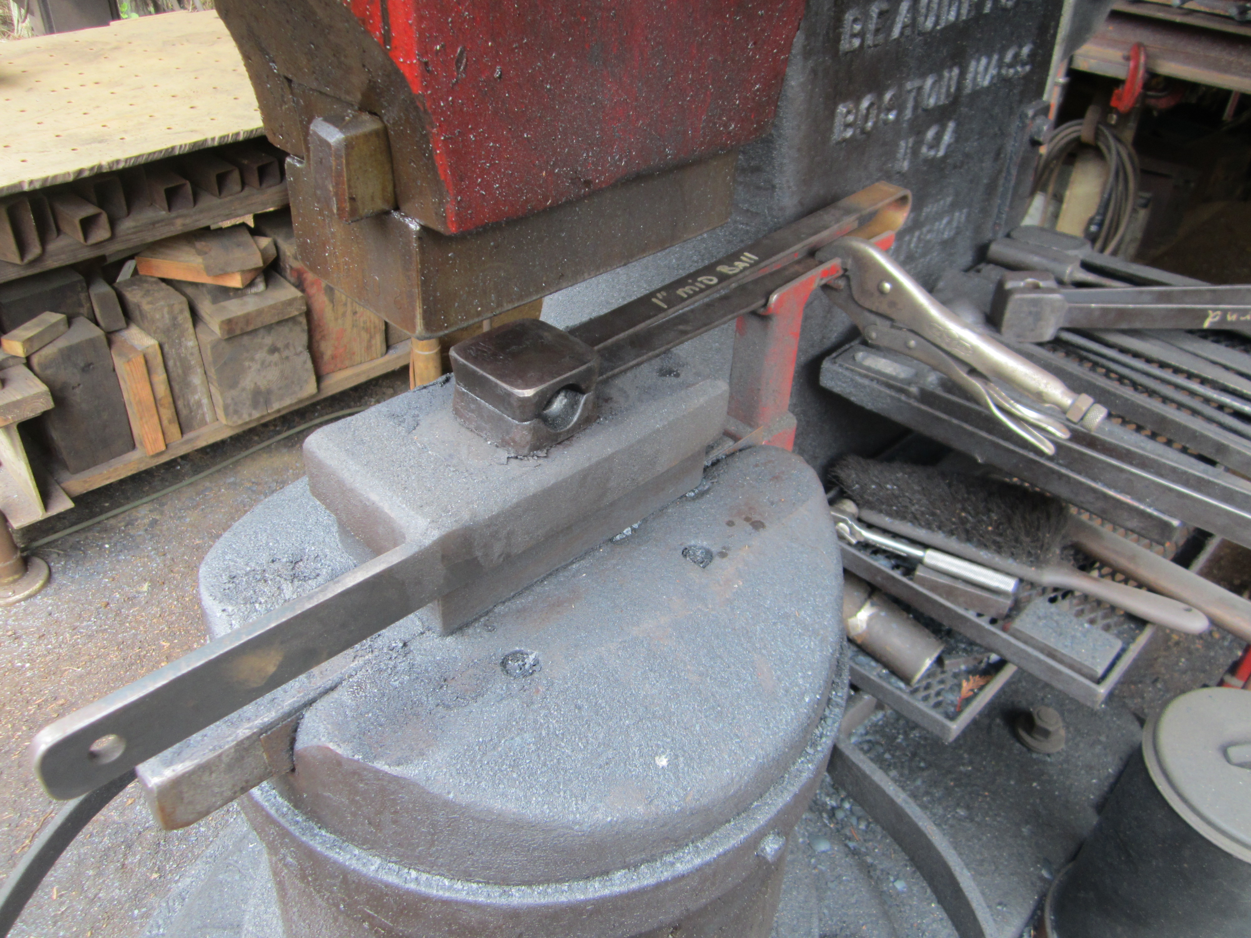
In actual use , there's really not any more noise than normal hammer operation. The cover is fabricated from pretty heavy material and even though it's a loose fit , the tool holder holds the swage and cover down tight over the bottom die. I generally just use this if the swage is fixed in the hammer for a run of parts. If it's a quick one off operation where I'm holding the swaging tool by hand I tend not to use it and brush the scale off with the tool as it accumulates. Any inconvenience is outweighed by eliminating any extra wear and tear on the bottom die -
Protective cover for bottom die
beaudry replied to beaudry's topic in Power Hammers, Treadle Hammers, Olivers
Not noticeably louder than a 200# hammer hitting hard ! It's heavy construction means it doesn't bounce or get deformed in use. Has no one else has had that problem of the die getting chewed up from scale under the swage ? -
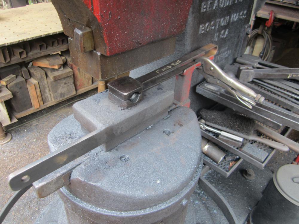
I was having trouble with the bottom die of my hammer getting chewed up from scale getting trapped under swages . The scale is very hard and abrasive and was being pounded hard under the swage in use, leaving the face of the bottom die pitted . My solution was to fabricate a cover for the bottom die from some 3/3'' flat bar and 1/2'' plate . One of the bars on the side was left long to act as a handle and the edge left sharp as a convenient edge to scrape scale off the hot bar before placing it in the swage. The cover is a loose fit so it's easy to place over the die and remove it when the swaging operation is done. Since the cover is mild steel it also doubles as a cutting plate under the hammer.
-
I had the same problem with the site where I built my shop. It's basically a lot of cut and fill work by hand or machine to get a level area big enough to work in. If it's a dirt floored smith shop it doesn't need to be dead level to work , but any machinery installed should be on solid foundation blocks and set as dead level as possible. Some kind of retaining wall will help hold the fill. Compact the fill as you build it up, so you don't have settling problems later. If it's just a hobby shop doing small work , you really don't need much more of an area bigger than about 10' x 10'
-
Adair, that looks like a good setup you did on the treadle and linkage. The factory setup on the Little Giants is a little sloppy. When mine was rebuilt, the hole in the frame for the pivot was reamed to size and a new machined pin fitted so the treadle pivots without noticeable slop . There is also a grease fitting to keep that point lubricated.
-
Adair, looks like an interesting modification to the back end of the treadle in that last picture. Care to explain what's going on there ?
-
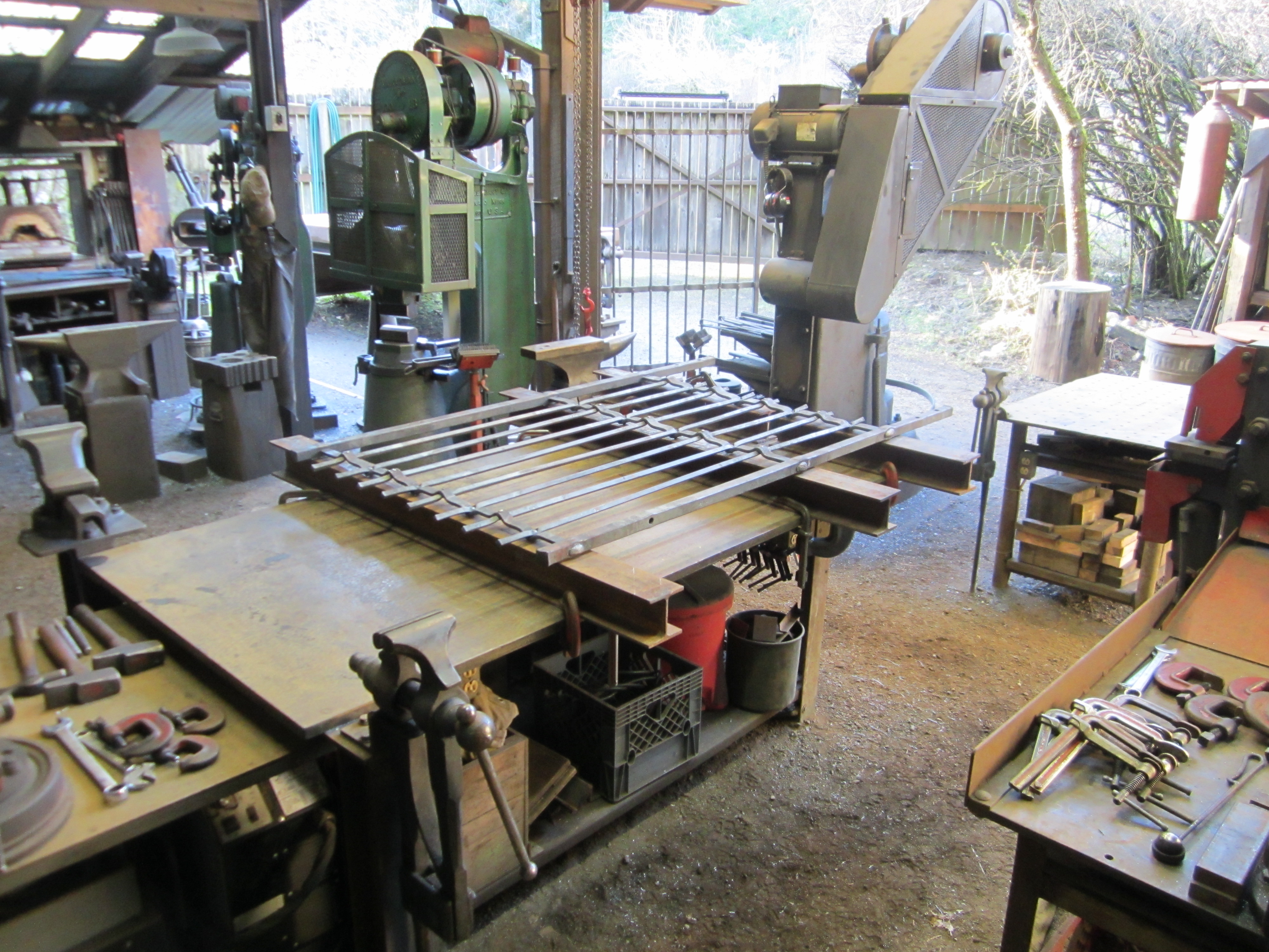
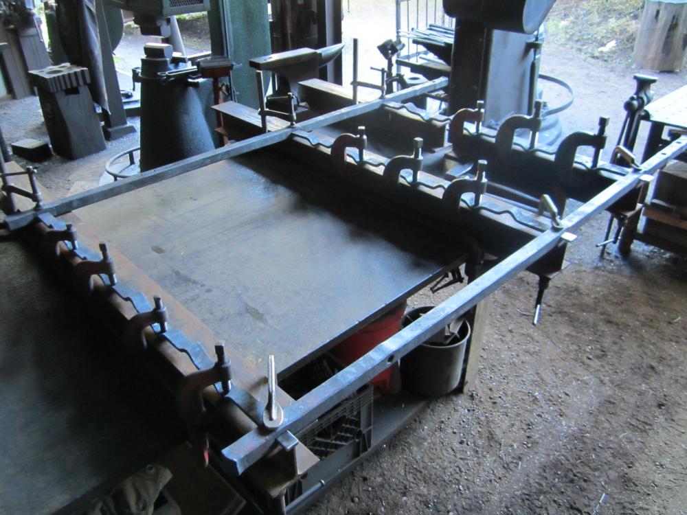
One way to expand both the size and capability of a layout work table is with wide flange beam sections. Wide flange or H beam sections are better than I beams in that the flanges are straight in profile rather than tapered so that clamps hold more securely. I use these if the project at hand is wider than my table or I need to clamp or need access in the middle or underside of the piece. In some ways this arrangement is better than a full width table in that by standing between the protruding beam ends , you can more comfortably reach into the middle of the table without to bend over so far. The picture below shows a set up for assembling the frame of a gate. The beams are laid out and clamped to the table square and parallel . The mortised side bar is clamped at the end of the beam and the cross bars with tenons are clamped tight to the beam with heavy fitters clamps. The tenons are headed off with a rounding hammer , a 4 # sledge and a punch, using a OA torch with a big cutting tip run through a gas saver for the heat source. After the tenons on both sides of the frame are set the vertical pickets are riveted in using the top of the wide flange and a small block as backing. Because the table is flat and heavy and the beams are set up square any inaccuracies can be corrected as the work progresses .

-
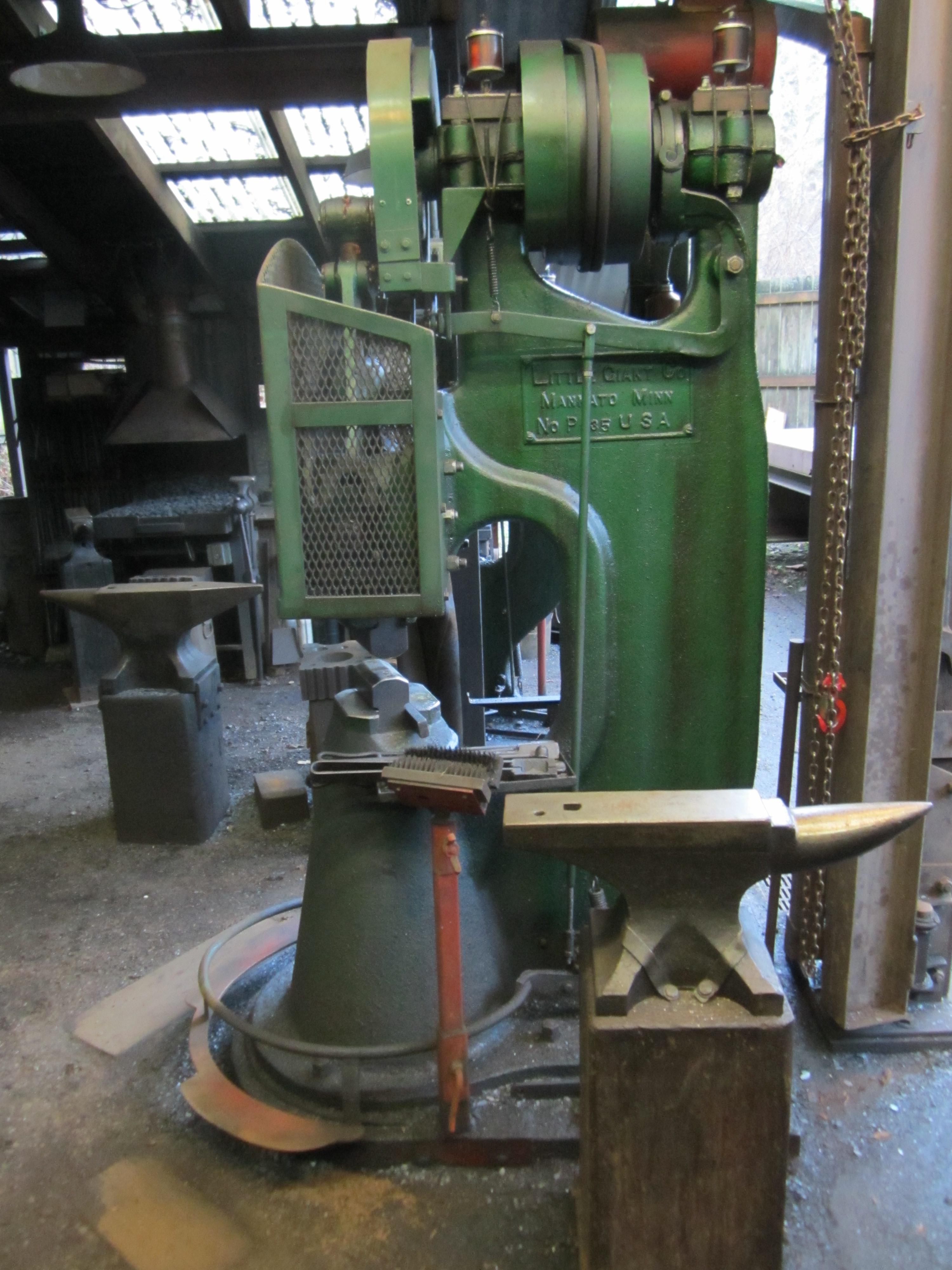
If you use your hammer for hand held top tool work ,a guard around the front of the hammer makes the operation much safer , so you can concentrate on the task at hand. Keep the bottom edge of the guard as high as possible for maximum visibility . Guards for hammers with nuts at the ends of the toggle arms need room for a pair of wrenches to adjust the tension.
-
Adair, you might consider making a guard for that hammer.Lot's of heavy moving parts going around right there at face level on those hammers. A simple flat bar frame with expanded mesh panels will provide both protection and visibility. The bolts that hold the ram guide are a good place to attach the guard. Mock it up with some plywood or cardboard to get the right shape and still have access to all the necessary adjustment and lubrication points. The guard frame also gives you a good place to mount the pivot points for a mechanical band brake over the top of the crank plate. Here's the one on my 100# hammer

-
Beaudry Hammer lubrication question
beaudry replied to beaudry's topic in Power Hammers, Treadle Hammers, Olivers
I read the same thing and I do keep a rag sitting in the pool of oil in the bottom of the ram cavity as well. I'm not sure if it does much to oil the rollers at the bottom of the stroke , but it keeps oil from splashing out when the hammer hits hard, Another trick I've used is to set a 4'' block of wood on the bottom die and let the ram fully down onto it. This effectively chokes the hammer at the bottom of the stroke and the rollers are visible through the oval hole in the ram. I can then squirt some oil on the rollers where they sit in the notches in the ends of the spring arms. I put a handle on the block and keep it handy so I can do this twice a day. A bigger or smaller hammer might need a different height block. I set the ram height on my 200# at 7/8'' at full down , which seems to give me the most useful stroke and power range for the kind of work that do. The rollers at the ends of the spring arms seems to be the weak link in the Beaudry design. When I first bought my hammer ,the right hand roller had been worn flat by a good 3/4'' and the left just a bit. I had new rollers made from heat treated 4140. Salem Straub, how is that big Beaudry working now that you've got it all back together ? -
I've noticed that I'm getting some scoring on the inside of the ram on my Beaudry #7 [200#] hammer , which is an indication that the rollers are not turning at the ends of the spring arm as they should. I'm religious about squirting oil down into that part of the ram twice a day when I'm running the hammer , but it is difficult to be sure the oil is getting where it needs to go to keep the rollers turning freely. I'm using Vactra #2 way oil for this as well as the ram guides, top bearing , idler bearing and all linkages as it seems to be designed for the purpose of heavy loads and low speed. I'm wondering if other Beaudry hammer users have had this issue and any tricks for getting the oil in there where it needs to go ? The hammer runs fine as is. The rollers were replaced about 12 years ago and the inside of the ram resurfaced at the same time.
-
I have a 7'' Columbian which is good for some things but a bit heavy and slow for most of the work that I do. My main vise is a 5 1/2'' Indian Chief that I like for it's nearly perfect size and heavy construction. As a result, I've worn out the screw box and had to built a new one to replace it. Those two as well as an 4 1/2'' Iron City vise are the only ones that I have that have a makers mark. Anyway , it sounds as if you made a good score for all that for $900. Let's see the rest of the pile.
-
It was a simple question, has anyone made a base like that ? and how does it work ? The two foot square of 5/16'' plate seems light for the purpose. This can be a difficult and frustrating craft to learn and the learning curve is long. Having a sturdy vise that doesn't bounce or move when you work on it helps a lot to lessen the steepness of that curve . Even if you have to have a moveable and temporary set up because of not having a dedicated shop space ,there are ways you could solidly anchor a vise to make it much more effective. The base plate could be held down tight to a wood floor with screws , into a concrete slab with lag shields , into a dirt floor with a buried block . A brace from the top of the post vise stand to a wall or heavy bench would do a lot to make it rigid . A few minutes work with a wrench or screw gun to set it up or take it down to clear the way is quick and simple. It's easy to patch the holes if you change your mind or have to vacate the space. Mocking it up is always a good idea for any new tool. You want to locate the vise with access to either side and front and some room behind it. It should be one leg of a work triangle between the forge, anvil and vise with only only a few steps between all three.
-
I'm curious , has anybody made a mobile base like that and how does it actually work in real life ? I have a hard time imagining it would be anywhere near stable and solid enough for all the things I use a post vise for; bending ,twisting , chisel and punch work, upsetting bars held lengthwise or vertically in the jaws with a heavy hammer etc.
-
50lb little giant dies
beaudry replied to skyforgemetalworks's topic in Power Hammers, Treadle Hammers, Olivers
I've had custom dies made by the folks at Little Giant and some big flat dies for my 200# hammer made by Bob Bergman at Postville Blacksmith Shop. These were all machined from 4140 and heat treated by them and have stood up well. I thought that the cost was reasonable and all it took was the time for a phone call and email and they showed up by UPS a week or so later. Whether it's more cost/time effective to make them yourself or to buy them from someone else depends on the capacity of your shop to forge or machine and heat treat a big chunk of tough and relatively expensive material . In either case you will have to spend some time accurately measuring the dovetails on your hammer and some time fitting the dies and die keys so that they stay tight.