Jump to content
I Forge Iron

Steve Sells

Administrators
  • Posts

    9,156
  • Joined

  • Last visited

Posts posted by Steve Sells

  1. I finished downloading from the wayback site, and have most of the 000 and 100 series online.   This leaves about half of the 200 series and most of the 500 series to locate

    Just keeping you posted on my progress.  My little vacation is almost over and I return to work Monday so I wont have as much time to devote to searching other archives, but if anyone has other suggestion, like the wayback site was, I am grateful for it, post it here or send me a PM

  2. IForgeIron.com Blueprints
    Copyright © 2002 - 2006 IFORGEIRON.COM, All rights reserved.

    BP00238 Simple Side Blast 55 Forge ©
    by Glenn Conner

    The name "55 Forge" is copyrighted, Glenn Conner 2004


    How do you quickly build a forge, that a beginner can use with little experience in construction techniques? The 55 Forge © Blueprint addressed that but required a little welding. The Simple Side Draft is another version of the basic 55 Forge ©, but without the fuss.

    Locate a pan, plow disk, bottom of a 55 gallon drum, or a flat piece of dirt. I chose the bottom 6 inches of a 55 gallon drum for this blueprint only because it was handy.

    _________________________________ There is a very real danger of explosion at this point.. If you picked up a drum that was reused and filled with a highly volital substance, you will not hear the BOOM. Even an original drum only containing only oil can be dangerous. If you have any concerns, or have never cut into a closed container before, pay to have these cuts made by someone else. Read and understand the disclaimer at the bottom of the page before you go any further. __________________________________

    Use caution if you cut into any 55 gallon drum or closed container.

    4sd090.jpg

    I grabbed the first pipe handy which turned out to be 1-1/4 inches inside diameter.

    Update: You MUST protect the edge of the drum. You can cut a 2 or 3 inch wide section from the drum. It will look like a hoop. Cut the hoop and fold it in half the long way so you now have a 6 foot long piece of metal that has a U shape. Place this over and around the edge of the drum to protect you from being injured. Drill several small holes in the drum and lash it down with wire.

    4sd094.jpg

    To leave a little ash to protect the bottom of the pan I placed it on a brick.

    4sd096.jpg

    I used additional brick to fill in the space till I could get enough ashes to replace the brick.

    4sd097.jpg

    Some old ash and clinkers in the middle and then started a fire using sticks from the yard.

    4sd098.jpg

    Add a little coal and you get a bit of smoke.

    4sd099.jpg

    The fire breaks through and the smoke is burned.

    4sd103.jpg
    As the coal catches fire the smoke is consumed.

    4sd106.jpg
    And you have a good bed of coals

    The fire did not have the aggressiveness I have come to expect from a bottom draft forge so I changed the pipe to a smaller pipe, this time another piece of scrap pipe with a 1 inch inside diameter.

    4sd279.jpg

    Wad up a couple sheets of paper and set them on fire.

    4sd281.jpg

    Add some sticks from the yard.

    A little air to get the sticks to burning.

    4sd282.jpg
     
    4sd284.jpg

    Then add a little coal to the top of the sticks and a little more air.

    4sd301.jpg

    It is indeed a little more aggressive fire with a more concentrated blast. Did not take long to get the 3/8 inch rod up to yellow temp.

    4sd305.jpg

    This shows the ball of fire that the Simple Side Draft forge produced..

    4sd307.jpg


    As a simple, quick to make forge, the Simple Side Draft 55 Forge © is worth considering. A section of pipe, an air supply, some coal and you can have a forge. It is not a complicated set up, and certainly will get metal hot enough to forge.

    Use what is available to you in your area. There are many ways to build a forge, and each has merit if it works. Assemble the parts and see what happens. Do not be afraid to change things. Keep what works and improve the design with each new model.

    Each forge and each fire pot burns a little differently. Find the sweet spot in the forge you are using and figure out what how to use that forge to it best advantage.

    Final thoughts: I have used the 55 Forge © with many modifications. I keep coming back to the original design because it works. Later designs eliminate the need to weld the air pipe which makes things even simpler. As stated earlier, this is NOT a heavy duty forge. It is NOT expected to last a lifetime, It costs little or nothing, and takes under an hour to build and works well. The 55 Forge © is a great forge to play with while you look for, or build your perfect forge. *** Disclaimer ***Life is dangerous. Use good sense in everything you do. Research and understand the dangers of each action before you start, and protect yourself and others. If you get hurt, you have only yourself to blame. The use of any electronic or printed information is solely at the user's risk.

    When you get enough money ahead, purchase or make a heavy fire pot and purchase or make a more permanent forge. This is just one step as you travel along the road of blacksmithing knowledge. Ask questions, learn, and ask more questions. then pass the knowledge on to others.

  3. Posted 05 December 2012 - 11:56 PM

    IForgeIron Blueprints
    Copyright 2002 - 2011 IFORGEIRON, All rights reserved

    BP0592 Knife Sheathe
    by Rich Hale and James Joyce


    finished.jpg

    If you make knives and would like to know how I make a sheathe, these pictures and text may help. Like everything we do there are many ways and this is only one. What I would like to show is how I fit a sheathe to a knife and how I sew the seam. Almost all of the tools I use are available from Tandy. This is not about stamping patterns but I will show when I do that in the pictures. Tandy has a couple of books that will help as will any of there latest catalog for finding supplies and tools. One book I like is how to hand sew. It is not a pricey book.

    sbp1-1.jpg

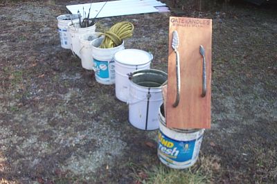
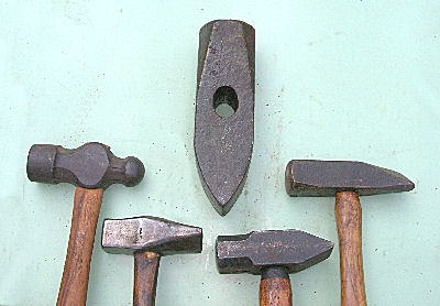
    List of the tools I use in this Blueprint. Starting from the left is an awl for marking on leather, a grover to cut into the leather where the stitching holes will go, an overstitch wheel that lays out the spacing for the holes, a hole punch for the rivet holes, dividers for laying out the area for the basket stamp pattern, skiving tool for tapering the billet, sewing awl with bobbin, sewing needle, mallet, thread and an old antler for shaping the finished sheathe around the knife handle.

    sbpcolors-1.jpg

    These are the products I use to dye my sheathes. The large bottle is the oil dye and the small is edge coat. I dye the leather several times until I get the look I like. I do the edges with the edge coat. I put on one coat with a cue tip and when it is dry I hands sand it. Another coat and it is smooth and nice.

    I use 8 oz leather for sheathes. I lay the knife on the leather and cut a large enough piece with the scissors that it will fold over the knife. The leather cuts better if you wet it first. Several time in this demo we will expose the blade to wet leather and if you have a carbon steel blade please take the time to wipe the moisture from your blade to prevent rust.

    sbp3-1.jpg

    I have placed the knife on the leather and trimmed the outside. making sure I have enough when folded over to leave room for the seam.

    sbp4-1.jpg

    This is a right handed sheathe. I have laid out the area for the pattern with the dividers and awl and have started the stamping. I used the grooving tool to lay out the line for the stitching. It actually cuts little shallow trench for the thread seam to lay into. I then used the overstitch wheel to mark where the stitching holes will be drilled. You just run the wheel in the groove and it spaces the marks. They sell wheels for different spacing's have them show you several and choose which you like. They are made to mark so many stitches per inch.

    sbp5-1-1.jpg

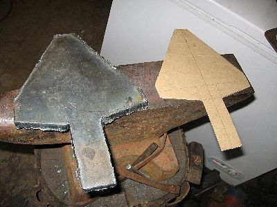
    I have marked up another piece of leather and laid it on the inside of the sheathe. I will cut this to match the blade and use it as a spacer, called a billet.

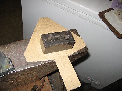
    I lay the knife on the billet and mark around it where i will cut it to fit. The billet is a key to making the knife fit into the sheathe nice and snug . And if you do not put a billet in and sew the folded over sheathe together the knife edge may cut the threads.

    sbp7-1-1.jpg

    I have cut the billet and laid it in place to show how it follows the edge of the blade and leaves room for the guard . The billet will need to be thicker on this sheathe to make room for the handle and guard.

    sbp8-1-1-1.jpg

    I have glued on two more piece of leather on top of the billet. You can use rubber cement for this to hold things in place for sewing but I prefer Barge cement.

    sbp10-1-1-1.jpg

    I use the skiving tool to taper the last two pieces I glued onto the billet. The tool has a blade in it and cuts when you pull it. You can also do this with a sharp knife or razor blade.

    P1010239.jpg

    The edge of the sheathe showing the billets, and how they taper down to make a smooth line along the edge. Sheathe is ready to be folded over and cemented in place.

    sbp%20edge-1.jpg

    After sewing I wet the whole sheathe with water and push the knife in and using my fingers and an antler I mold the sheathe around the knife so it fits nice. I then remove the knife and let the sheathe dry in the sun. I then use a belt grinder to dress the edge of the sheathe and smooth it up so all pieces of the billet and outer layers appear as one. I use a 120 grit belt for this, You could shave the edge with a blade and hand sand the edge.

    11-1-1-1-1.jpg

    I have a small block of wood clamped to the drill press table to provide a back support for the leather when I drill with the 1/16" drill.

    sbp12-1-1-1-1-1.jpg

    Drill through the sheath using the marks you made with the overstitch marking wheel as a guide. Use care to keep the sheathe flat so the holes exit the back of the sheathe in a straight line.

    sbp13-1-1-1-1-1.jpg

    Sheathe is all glued up and in stitching horse I start the first stitch in the second hole and pull about 20" out the other side for this size sheathe.

    sbp14.jpg

    I have pulled the thread through and attached a needle to it,, the needle always stays on the side away from the stitching awl.

    sbp15-1-1-1-1.jpg

    Go into the first hole now. when you push the awl through and pull it back a little bit it will leave a small loop on the other side push the needle through that loop and then pull withdraw the awl,,pull evenly on the strings from both sides so they make a nice tight stitch keep the tension the same all through the sewing for nice looks.

    sbp16-1-1-1-1-1.jpg

    When you get to the end of the sheathe start back and sew about three or four hole to lock things tight. Then push the awl though and put the needle like this. pull the awl out and the needle will keep a loop of the thread on the back side ,,pull that loop out a bit and cut the awl loose. Now you have both ends of the thread on the back side. cut them short.

    Now its the time to put some finishing touches on the seam.

    Lay the sheath on its face side on something nice and hard and real smooth. Tap flat on the back of the seam all down its length with the mallet. Then take the overstitch wheel and run down the seam on both sides of the sheathe. this makes the stitches look real clean.

    sbp17-1-1-1-1-1.jpg

    Different styles of knives may take different types of sheathes. We covered the fold over push type and this is a flat sheathe sewn all around. to fit this sheathe you would make a billet like in the demo and it would go all the way around the knife and be sewn in like the other but this would only need to be one layer between the front and back pieces. I hope this gives you and idea on where to begin or may just let you know that how you are doing your leather work is better than mine.

    finished.jpg

    This is what all the work has been about. I feel that when I spend a lot of time on a knife it is only right to compliment it with a well fit attractive sheathe.

    Special thanks to Jim Joyce for flying in to take the photographs, And to my hands for the modeling assignment.
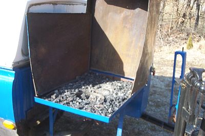
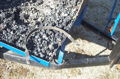
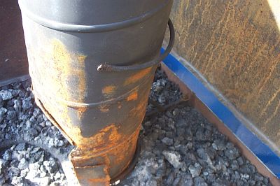
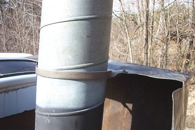
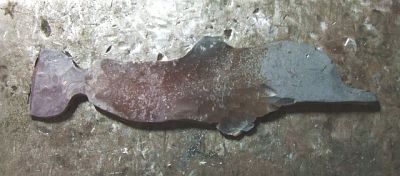
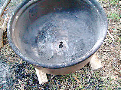
  4. The Articles and Stories have been cleaned up and moved over now.

    I don't know how but the update that glitched and removed so many photos way back when,  also inserted sometimes as many as 12 blank lines in the middle of the text so I hope those are getting easier to read now that they are fixed.

    Sorry it took so long, but I had to wait til they were available to clean up before I could do anything with them,  Glenn was collecting what he found, but was not in a rush to get them ready, after being offline for so long. 

    Do to a few broken links that I can still read in his notes,  I think I may have found there is a directory in Glenn's computer Hard drive of his back ups that can access the pictures.  He already moved many over to this system,  While neither  I nor this program,  have access too that Hard Drive, FOO does, so in time when he gets back to WV if they are there, he can put those somewhere available to me and I can load them in and get the rest of the 250  or so remaining BPs online again as well.

    that's it for now


  5. IForgeIron Blueprints
    Copyright 2002 - 2011 IFORGEIRON, All rights reserved

    BP0502 Wrench Holder
    by irnsrgn


    wrench1.jpg

    Many times a tool box looks like this, wrenches every where and you have to search for the size you want.

    wrench2.jpg

    An old trick is to use a compression spring as a wrench holder to help organize things.

  6. IForgeIron Blueprints
    Copyright 2002 - 2011 IFORGEIRON, All rights reserved

    BP0532 Get what you pay for, with no waste
    by Glenn Conner


    How many times have we collected buckets and barrels of scrap and then thrown them away. That is actually money in those containers, and we throw it out.

    Stock comes in 20 foot lengths from the steel yard, which can be cut into 2 each 10 foot sections to be easily hauled. Once back at the shop it can be placed into storage as a 10 foot length will fit diagonally on the ceiling of even small shops.

    Then it can be cut into 4 each 5 foot lengths (60 inches), 5 each 4 foot lengths (48 inches), 6 each 40 inch lengths, 8 each 30 inch lengths, 10 each 24 inch lengths, 12 each 20 inch lengths, 15 each 16 inch lengths, 20 each 12 inch lengths, and etc.

    The 48 inch section can be cut into 3 each 16 inch lengths, the 30 inch section can be cut into 2 each 15 inch lengths, the 16 inch section can be cut into 2 each 8 inch lengths, and the 60 inch section can be cut into a 36 inch length and a 24 inch length.

    Design or re-design your porjects on the following lengths of stock,

    120, 60, 48, 42, 40, 36, 30, 24, 20, 18, 16, 15, 12, 10, 9, 8, 6, 5, 4,

    That is 19 different lengths of stock and NOT ONE BIT OF WASTE !!

  7. IForgeIron Blueprints
    Copyright 2002 - 2011 IFORGEIRON, All rights reserved

    BP0551 Demo Trailer
    by Ptree aka Jeff


    Opening disclamier;

    This is a demo trailer I built. Building a trailer is a job only for those with very good welding skills and for someone willing to assume the risks of design of a road going vehicle. If you do not feel comfortable with building the actual trailer, trailers are available on the used market very cheap. Just use a commercially built trailer as the starting point.

    I built this trailer for a Indiana Blacksmithing Association competition as a do at home project. Scrounging and unusual materials counted for extra points. The actual as built cost for this trailer was less than $50.00. I only bought the hitch coupler, and new trailer lights. Later after I had won the contest, I noticed that the springs were badly worn, and I did not like dragging the differential, so I replaced the springs with new units from TSC, and gutted the differential. I turned the differential over, cut the ends of the housing off and welded the mounts from a mini-van rear axle on the ends. Then the bearing hub assy from the mini van, and NEW tires scrounged from a neighbors secret stash. I traded him some Bar-B-Que tools for those. I already had the blower, the drill press, and another neighbor had this old Datsun truck in his field rotting. He gave it to me to haul away. The tool box was a scrapped industrial electrical control panel box, gutted and all the holes welded up. This trailer has an extended frame to get the axle located correctly. It trails perfectly, and now has perhaps 3000 miles on it.

    058.jpg

    Trailer ready to travel

    002.jpg

    Forge is folded up and rain cover on the vise.

    004.jpg

    Offside with tool box.

    006.jpg

    Lots of stuff in a small space!

    008.jpg

    Stack for forge is stowed on the roof.

    009.jpg

    Vise is uncovered.

    010.jpg

    Forge wind shield is folded up.

    011.jpg

    Hooks for fire tools are hung on forge edge, stack clamp readied.

    040.jpg

    Stack is placed on peg in forge rear.

    013.jpg

    Clamp is installed.


    014.jpg

    Forge is ready for the fire.

    015.jpg

    Now to unload. Note legs that engage the floor grooves, holds table steady.

    016.jpg

    Other end has fixed wheel to allow rolling the long table out. This is a breeze to roll out and unload as you go.

    017.jpg

    Table with the legs flipped and inserted into the same socket that held them for travel, but from the bottom.

    038.jpg

    All this stuff was stowed on the table.

    018.jpg

    Table has back bar to hang stock from to display, and projecting arms to hang dinner bells from. The little kids love these bells and I invite them to come over and ring. They drag the adults along:) Also keeps the little hands off the other stuff on the table. These are low enough for a 3 year old to ring.
    019.jpg

    Next the drill press is pulled from stowage.

    020.jpg

    Drill is mounted.

    042.jpg

    On a drop on mount. Note cut outs in channel for lightness.

    021.jpg

    Next the remaining tables are pulled out. Another roller rack, shorter to clear the blower.

    022.jpg

    Table legs drop on...

    023.jpg

    pegs on the rack. these help hold the racks easel and table upright.

    024.jpg

    Blower is now exposed inside the box, out of the weather.Note protective cage and compact spare tire.

    025.jpg

    Blower feeds the fire pot made from a trailer steel rim with one tire bead flange cut off.

    026.jpg

    Blower crank is through the side of the box.

    027.jpg

    Rigged to demo! just add the fire, stock on display, and a crowd. I left the anvil in the shop, but it and its mount alo stow in the box.

    028.jpg

    The tool box is made from a gasketed door industrial control panel. Holds plenty and is rain tight. I added a shelf, and hooks for fire tools.

    029.jpg

    Drop down shelf is very handy.

    033.jpg

    Note the extended frame to allow trailer correct geometry, to trail correctly.

    034.jpg

    Stock racks, rubber bungee is where the 70# demo anvil rides. Stand for anvil just behind once loaded.

    I use this trailer, mostly loading and unloading by myself. All the tubing is thin wall, 16ga. Makes the tables and so forth very light.I can easily carry the long table by myself without straining. The plywood table top is 6mm plywood salvaged from crates, but 1/4" from the big box store would work as well. I can unload and set up and have a demo ready fire ETC in about 40 minutes from unhooking the trailer. If one of the kids is helping make that 20 minutes. I can leave much of my demo equipment in the trailer all the time and it stays dry and out of the way. Also nice to hide the tools if a rain shower approaches during a demo.
    The pick up I used was a standard length Datsun from way back. Sitting useless in a neighbors field. He wanted it gone and I made that happen. I cut off the cab portion, saving as much of the frame as possible. I salvaged the torsion bars from the front end, and the remainder went to the scrap yard. The fiberglass cover was sound but had had a pass through so I had to fill the front in. I had to patch many rusted spots in the bed. But still cheap.

    I made sure that the frame parts I retained were sound and reinforced a couple of area that may have been thinned with rust. I ended up eventually replacing the axle with a rebuilt free wheel unit I made up from odds and ends. An aluminum topper would have been much lighter, but most this age are bad leakers. A taller topper would be very nice, as would a bat wing topper. I haul my demo trailer with a E-150 econoline with a 302 and it pulls really nicely. Very steady with no weave. It would be nice to have brakes, as I figure I may have 1000 to 1500# all up. Still petty light.
     

  8. IForgeIron Blueprints
    Copyright 2002 - 2011 IFORGEIRON, All rights reserved

    BP0552 Dolphins
    by Bill Epps
    photos by Bill Epps and Richard Thibeau


    Dal-1.jpg

    I start with a piece of 1/4" X 1" flat bar and set down what will become the snout

    DolphinI.JPG

    The snout formed and the head started to round back

    Dal-3.jpg

    After rounding the front of the head start tapering the body

    Dal-4.jpg

    Start forming the end of the body leaving the stock width that will become the tail

    Dal-5.jpg

    Use the corner of the anvil to start the dorsal fin (just like drawing a clip on a horseshoe)

    Dal-6.jpg

    Drawn out dorsal fin

    Dal-7.jpg

    Use a round head punch to start the flipper fins (like a bob punch )

    DolphinF.JPG

    Cut the piece off the stock

    DolphinE.JPG

    Put a 90 degree twist at the end of the body to make the tail flat with the body

    DolphinD.JPG

    Take a good heat and hammer the twist out to make it smooth with the rest of the body

    DolphinK.JPG

    Now the twist is blended in to the rest of the body

    DolphinJ.JPG

    Punch the eye and chisel the mouth

    Dal-16.jpg

    Using a sander polisher (not a angle grinder ) with a cup wire wheel at a red heat I clean up the piece

    Dal-17.jpg

    Dolphin from 1" flat bar a little skinny

    DolphinA.JPG

    Dolphin from 1 1/2" flat bar makes a fatter critter

  9. IForgeIron Blueprints
    Copyright 2002 - 2011 IFORGEIRON, All rights reserved

    BP0572 How to make Charcoal
    by Jaco aka James Flannery


    SANY0018.JPG

    The empty tub with holes in bottom. Just an old washing machine tub with holes in the bottom. Set on a couple of pieces of wood to allow air to circulate up through the holes in the bottom of the tub.

    SANY0022.JPG

    Start a fire with cardboard and small wood scraps. Wait a few minutes.....

    SANY0023.JPG

    Add some dry wood. About 18inches long......that's the size that fits the tub......split to 2 in. x 2 in. more or less.. wait a few minutes.......

    SANY0024.JPG

    The wood burns down and the fire gets hotter. Add more wood. I want the tub to be as nearly full as possible.

    SANY0020.JPG

    This is some wood from a previous burn that did not char completely. I add it last since it doesn't have far to go to become charcoal.

    SANY0026.JPG

    Since I got in a hurry and added all the partially charred stuff all at once, there was some smoke.

    SANY0032.JPG

    The smoke burns off and I have a hot fire of heaped wood.

    SANY0033a.JPG

    A piece of sheet metal from an old animal feeder serves as a lid. A metal barrel lid will do the same thing.

    SANY0034a.JPG

    When the wood burns down a little more, the lid will settle on the the tub rim making a fair seal......but certainly not airtight. When I put the lid on the tub, I also kick the wooden supports out from under the tub to help seal the air holes in the bottom.

    SANY0037a.JPG

    I always put something heavy on the lid to keep the wind from blowing it off the tub.
    I usually fire this thing up in the evening and let it burn through the night. I always set the tub away from buildings and anything else that might be combustible. A typical burn usually yields about a 5 gal. bucket of charcoal.

    SANY0058.JPG

    The next morning, the charcoal was still smoking just a little.......so I dashed a gallon or so of water in the tub.

    SANY0042.JPG

    This is what the charcoal looks like in action. This is one version of the semi-direct method for making charcoal. I do it because it's easy and simple. It takes longer to explain it than it takes to do it.

  10. IForgeIron Blueprints
    Copyright 2002 - 2011 IFORGEIRON, All rights reserved

    BP0578 Head Rest
    by Glenn Conner, Whitesmith aka Sean Conner


    The hood and sides were removed from the yard tractor and Whitesmith was fixing something but every now and again there was a crunching type sound.

    26.jpg

    This was one of the moments when you just have to stop and ask, what ARE you doing? Working on the tractor was the reply.

    29.jpg

    What is that crunching sound?

    31.jpg

    Oh that. I got tired of holding my head in the air while I worked. So I got a head rest. It makes things a lot easier.

    I am going to try this on out of position welding next chance I get. Who says you can not learn a trick or two from another blacksmith.

  11. IForgeIron Blueprints
    Copyright 2002 - 2011 IFORGEIRON, All rights reserved

    BP0584 How to store a chain
    by Glenn Conner, Whitesmith aka Sean Conner


    25.jpg

    Is this how you store your chain? There is an easier way you know.

    20.jpg

    Get a old one gallon paint bucket. Start one end on the chain into the bucket.

    21.jpg

    Keep feeding the chain into the bucket till you run out of chain.

    23.jpg

    Pick the bucket up by the handle and be happy. To use, just grab the hood and pull the chain out of the bucket.

    To keep the chain from rusting, spray it with a little automatic transmission fluid.

  12.         IForgeIron Blueprints

    Copyright 2002 - 2011 IFORGEIRON, All rights reserved

    BP0553 Building a Brick Forge - Part 1
    by Jeremy Knippel 2006


    BF30.jpg

    I will try to explain the best I can on how I built this forge. Nowing that if you build a forge similar to this, you may be using mat'ls of different sizes and or re-design it to fit your needs. I'm including a lot of pictures so that any cement contractor / or yourself can see how it's done and use their / your judgement as to any changes or modifications. These are the only pics I took during construction. If I don't have a clear picture of something I will try to explain it as I go.

    *******This is just my design and may not be the best way or the right way to build this.*******

    BF1.jpg

    In the backround is a couple pallets of bricks worth and this shows the future placement of brick forge.

    BF2.jpg

    These are the dimensions for the brick layout. The 2 side arches are not dimesioned but as you will see in the following pics - you will understand how they are in relationship to the rest. All they are for is access to the ash dump and extra storage under the forge, so they do not need to be any place exactly. The 24" dimension is the depth of the chimney from the firepot up,(again later pics will explain).

    BF3.jpg

    This is the start of the lay out so the contractor can get a feel for what is wanted. The row next to his hand will be moved over toward him so the 2 bricks on top can be placed in between the 2 side rows so the width is 3 brown bricks an 2 red half bricks.

    BF4.jpg

    This is the start of laying the bricks. The red half bricks for the borders are set out from the brown bricks by a 1/4" for a bolder look. Concrete ties were used ( shaped in a U and inserted in the holes of the bricks and core filled) to help hold the border bricks to the rest of the main ones.

    BF5.jpg

    Another view of the start.

    BF6.jpg

    Working on the base of the chimney.

    BF7.jpg

    The bricks are layed up to were the arches will set now.

    BF8.jpg

    This is the start of puting in the archways. The arch support is made from 1/4" x 6" flat steel. Each end has a 1"flat extension to set on the bricks. Being the arch supports were made from mat'ls at hand I had to put a rod support on the back side to hold the arch from tipping inward during the brick installation.

    BF9.jpg

    Laying the top row of red bricks for the (coal tray and fire pot support - # 2 in the series of 3).

    BF10.jpg

    Another view.

    BF11.jpg

    The brick work is done and ready for the chimney floor (will be the same level as the coal and fire pot level).

    BF12.jpg

    The base below the chimney was filled with extra and broke blocks for filler and filled with cement. I used a 6" galvanized pipe for a clearance hole for the 3" air intake pipe. This is a critical measurement as far as height, so that after everything is done your air intake pipe will fit into the bottom of your fire pot. Also you can see were the back of the arch was filled with mortar and smoothed upward (as a fillet weld), this may not be necessary but I did it for extra support for the arch bricks.

    BF13.jpg

    Fire brick was used for the inside of the chimney area. Measurements are approximate - I did not measure these during assembly - I tried to get them afterward the best a could. These are as close as I could get - you may have to slightly change these measurements as needed.

    BF14.jpg

    Laying the brick up as the chimney is being done. The chimney opening is starting to take shape.

    BF15.jpg

    The opening is almost done(14" wide, 16-1/2 " tall, and 17-1/2" at the middle of the arch). The arch support on this one is temporary - it was removed so that there was no problem with different heat expansions between the metal and brick.

    BF16.jpg

    Things progressing along good.

    BF17.jpg

    By this time I was getting pretty exited as to how it was looking.

    BF18.jpg

    BF19.jpg

    View looking down the chimney.

    BF20.jpg

    Another view.

    BF21.jpg

    Starting the tapering of the inside of the chimney.

    BF22.jpg

    Tapering the sides inward so the 12"x12' flue will have a place to set.

    BF23.jpg

    Another view.

    BF24.jpg

    You can see were the inside of the transition of the taper is plastered over with mortar to make smooth for the smoke. Also there is a smoke shelf just above the top firebrick row across the back.

    BF25.jpg

    The rest of the outer bricks were brought up to the clay tile area and the first clay tile flue was set.

    BF26.jpg

    Another view.

    BF27.jpg

    From the bottom of the 12 inch x 12 inch flue up - insulation was put inside the gap between the outer bricks and the flue. This helps to speed up the heating of the flue to start the smoke draw. This was done all the way to the top of the chimney outside above the roof.

    BF28.jpg

    Another view, ready to go through the roof.

    BF29.jpg

    Plastic was put on the tapered area to keep motar off while proceeding through the roof.

    BF30.jpg

    All the brick is done, acid washed, and sealed. The chimney above the inside ceiling was made with regular block around the flue and built up to the recommended height according to the distance from the peak of the roof. I made a stainless steel roof jack for were the chimney exits the roof outside.

    That's how I built my forge -Jeremy Knippel

  13. This was taken from an email to assist a member in trying to get a good forge weld.

    To start let us discuss colors of hot steel.

    Lessons in Blacksmithing
    Copyright 2002 - 2007 IFORGEIRON, All rights reserved.

    LB0007 Seeing Colors
    Explanation of colors:
    I divide red, orange, and yellow (the colors of heated metal) into 3 groups each. Start with black then low red, medium red and high red, low orange, medium orange, and high orange, low yellow, medium yellow, and high yellow, then white heat. This is followed by sparks. The lower temperatures have more separation in heat colors than the separation in heat colors at high temperatures. The difference is suttle, and everyone sees color differently. The same colors are different temperatures in bright sun then in shade and may differ by as much as 2, 3, or 4 color levels. You need to standardize to your conditions. The 12 color divisions (black to sparks) are enough for discussion purposes, and are repeatable under YOUR conditions.

    This is the time you need to find a steel yard and purchase some NEW mild steel stock. Put the metal into the fire and get it hot enough to throw sparks, just like a 4th of July (USA) sparkler. This is usually when the metal is beyond high yellow or white in color. You have now successfully burned the metal, don't do it again as that is TOO HOT. Cut the burnt end off the stock to where there is new material.

    Put the stock back into the fire, heat to high orange or yellow, and hit it with a hammer. It will move a certain way under the hammer each (every) time. When the metal gets to low orange in color by loosing heat, it will stiffen a bit. Warm it back up and do it again at orange in color, hammering the metal while it falls to medium red in color. Put it in the fire and bring it only up to showing low red in color. Hit it with the hammer and feel how it moves (or doesn't want to move). Back to the fire and then repeat at yellow. Feel the hammer when it hits the metal at different temperatures. If you see the color of the mild steel as red stop and take another heat, get it back up to working temperature.

    Different types of metal act differently at the same heat color. Some metals have short working temperatures, meaning that they only should be worked at medium to high yellow for instance. If it gets to low yellow quit and take another heat. This is something you will have to either learn on your own or seek the advice of others that have worked this type steel.

    Your eyes see colors differently then how others see and label the same color due to age, glasses, and life experiences. You are building YOUR heat standard for YOUR forge under YOUR smithy conditions.

    During the next week, look at different objects in your part of the world and *see* the color. Then label that color as black, reds, oranges, yellows, white. The practice will aid you when you get to the forge and being able to tell the sometimes suttle differences in colors. If you really want to know what temperature a specific color represents, or what temperature a piece of steel has been heated to, purchase a temperature measuring device called a pyrometer. There are also wax pencils that can be applied to the steel that will melt at a specific temperature. Both work well and are more than accurate for use in blacksmithing.

    Now that we have the colors so we can talk to each other. Try the following

    Run the fire deeper so you have more available heat with less oxygen getting to the steel. Put the anvil beside the forge, one step away so you do not loose heat or time. Practice the dance of going from the fire to the anvil in one smooth quick motion.

    With mild steel, wait until it throws the second spark and hit the weld as it throws spark #3 (or try to).

    Bump the metal to make the forge weld. This can be done with a piece of wood such as a broken hammer handle minus the head. Just hold it vertical and bring it down and bump the metal. The photos that you see where blacksmiths spray sparks all over the smithy is just Hollywood effects as those sparks are your weld being scattered to the 4 corners of the shop. You can touch the two pieces of metal together in the fire and when everything is right they will weld together, at the touch point,right there in the fire.

    Once you bump the metal together on the anvil, go back to the fire and reheat to the 2nd spark again. This time bump the metal with the hammer head to complete the weld. Let it cool to high yellow and then hammer it into shape.
    :
    Larger material (1/2 inch and above) welds easier than smaller material as it holds more heat. You can put a piece of heavy metal (say 1 inch plate) in the forge, get it to low red, and use it as the anvil to bump the weld together. The hot plate will not suck the heat out of the weld like a cold anvil will do.

    Practice is the key, A couple of welds every time you build a fire and you will figure it out quickly.

    FLUX, flux is not glue. It helps but is not needed. A wire brush to remove any scale at orange heat, again at yellow, is all that is needed in most cases.

    Read about scarfing or shaping the ends to be welded so they push out any slag or junk as the weld is being made. You want to upset the ends a bit so you will have some extra material in the weld. You then pound this material back into the stock once the weld is finished. Otherwise you may have a thinning of the material at the point of the weld.

    Hope it helps as there is no magic to making a forge weld, just figuring out how it is done and then like anything else you want to get good at doing, lots of practice.

  14. IForgeIron Lessons in Blacksmithing
    Copyright 2002 - 2007 IFORGEIRON, All rights reserved.

    LB0004 BP925 Blacksmithing Hammers


    Hammers

    Blacksmiths use many different hammers, hand hammers, foot operated hammers, motorized hammers, steam hammers, pneumatic hammers, and others. As you are just starting, we will discuss hand hammers.


    372.jpg
    These are NOT hammers. You may sometimes see them being used as hammers, but that is both wrong and dangerous. They are NOT hammers, and should not be used as such.


    356.jpg
    This is a carpenters hammer not a blacksmiths hammer. It will work but is not recommended.


    357.jpg
    A ball peen hammer or machinists hammer is a much better choice for starting out in blacksmithing. There is usually one somewhere in most garages, at flea markets, or junk stores. Most people will want a hammer with a head that weighs 1-1/2 to 2 pounds.


    358.jpg
    While your looking for the ball peen, see if you can locate a mini-sledge, again with about a 2 pound head weight.


    365.jpg


    366.jpg
    A cross peen hammer (top hammer in both photos) has the peen cross ways (90 degrees) to the direction of the handle. The straight peen (bottom hammer in both photos) has the peen in the same direction as the handle. Either one with a head weight of about 2 pounds or less is what most blacksmiths use.


    359.jpg


    360.jpg


    363.jpg


    800h.jpg

    The peen may be of different shapes but all three of the above are still called cross peen hammers. The bottom hammers are Hofi hammers, one cast type, one forged type.


    361.jpg
    This peen is turned 45 degrees to the right and is called a slash peen, or diagonal peen, or right handed diagonal peen.


    362.jpg
    This peen is turned 45 degrees to the left and is called a slash peen, or diagonal peen, or left handed diagonal peen.


    367.jpg
    Here you can see the left handed diagonal peen, cross peen and right handed diagonal peen.

    The difference in use is the blacksmith being right handed with the hammer in the right hand, they still have the ability to see where the hammer is hitting the work. If they were to use a left handed diagonal peen, the peen would block their view of the work.


    370.jpg

    371.jpg
    The hammer shown are ball peen, left handed diagonal peen, straight peen, cross peen and right handed diagonal peen.


    How to hold the hammer

    You should grip the wooden handle in such a way it is comfortable to you, thumb down and against or close to your fingernails. If you take a couple practice swings in the air, you will find the distance from the hammer head that is comfortable to you.

    You need just enough grip on the handle to keep it in your hand when you swing the hammer. The shoulder, arm, and wrist are all involved in the swing. Keep the elbow next to your side. As you gain more control of the hammer, you will adjust the distance between the hammer head and the grip point. Many times only an inch or so makes a large difference in comfort.


    Hammer control

    One of the things you need to learn is hammer control. That means how to hold the hammer, and how to hit where you want the hammer to hit. Start 5 or so nails in a block of wood. How take your hammer and hit each nail one time. Continue hitting one nail at a time while you vary the pattern. Practice is what makes the hammer go where you want and hit where you want.

    With a pencil, put 5 or more random X's on a piece of pine sheeting or other soft wood. Place the board on the face of your anvil. Now hit each X one time with the hammer. You should see a pattern to the imprints in the wood. A crescent means you do not have a square hit. Crescent at 12 o'clock means the board (anvil face) is too low, at 6 o'clock means the board (anvil face) is too high, left or right is how you hold and or swing the hammer. Your objective is a circular impression with the X in the middle.

    This is not a one time project, but a practice that you should do until you gain hammer control. It is also a good way to check the height of the anvil and how you hold your hammer. Use the wood at the beginning of the forge session and again at the end. Compare the impressions. Make changes in your technique if needed.


  15. no clue, its a Glenn number system. I honestly think its based on when it was presented as much as anything

    everyone should be able to read and post to the forum sub section,. the Pages will be going away after I finish up, I have been deleting from there as I transport them into the forum itself

  16. IForgeIron.com Blueprints
    Copyright © 2002 - 2011 IFORGEIRON.COM, All rights reserved.

    BP0903 Vise Stand
    by Pascalou

    Posted 11 January 2009 - 05:34 AM


    Hello

    Here a vice stand.an alternative of the system of displacement of the anvil stand of " markb". weight: approximately 130 kg
    A+ P.L

    01.jpg

    02.jpg

    03.jpg

    04.jpg

    05.jpg

    06.jpg

  17. IForgeIron.com Blueprints
    Copyright © 2002 - 2011 IFORGEIRON.COM, All rights reserved.

    BP0904 Vise Stand
    by Iron Falcon 72
    Posted 22 February 2009 - 09:01 PM

    Here's a new post vise stand I just finished by modifying the green base. This is a small vise, 3.5". I have a larger one that needs a new spring and wedges. It will be next.
    The stand was originally set up with a chain saw sharpener on top. Got it and the sharpener for $50. The sharpener's table is shown with the post still attached where I cut it off. I had no idea the post was solid but my Milwaukee "The Torch" cut-off blade went right through it.

    The new top is all scrap from the junkyard. I hadn't done any welding in about a year so it started a little rough. I plan to store tongs and hammers on the sides and end.

    The only markings on the vise are the numbers shown. The "35" may refer to it's size. I know it's not much to go on but, does anyone recognize the brand?
    I'm sure that there are better arrangements for the tongs and hammers but, I have only a small area to work in (6x8) and no room for another rack. And at this point I don't have so many of either.

    I'm not sure how much it weighs. The flat bottom actually makes it less stable. It rocks on every little bump on the floor. When I decide where it will finally reside I will bolt it to the floor.

    01.jpg

    02.jpg

    03.jpg

    04.jpg

  18. IForgeIron.com Blueprints
    Copyright © 2002 - 2011 IFORGEIRON.COM, All rights reserved.

    BP0905 Vise Stand
    by Frosty
    Posted 08 April 2009 - 09:45 PM

    How handy the vise stand thread comes up now. I just finished a folding vise stand I started before my last surgery took me out of action for a while.

    01.jpg

    I added a couple chachkas to hold hardy tools, hammers and my twisting wrench. There's a 3/4"+ lip around the plate behind the vise so I can lay tools on it and keep them handy.

    It has one coat of paint, will get another and a little gold trim to match the vise, my shop colors are green and gold.

    Frosty


  19. Posted 22 July 2011 - 09:27 PM
    IForgeIron.com Blueprints
    Copyright © 2002 - 2011 IFORGEIRON.COM, All rights reserved.

    BP0906 Vise Stand
    by Andrew OC
    Posted 01 March 2010 - 07:16 AM

    Hi y'all,
    here is a vice my TAFE college has used for an age. The origins of the cast iron trapizoid are lost in the mists of time. It is quite heavy, just movable with a long bar.enjoy

    01.jpg

    02.jpg
    AndrewOC

  20. Posted 22 July 2011 - 10:27 PM
    IForgeIron.com Blueprints
    Copyright © 2002 - 2011 IFORGEIRON.COM, All rights reserved.

    BP0907 Traveling Vise Stand
    by Vance
    Posted 24 August 2010 - 04:28 PM

    Since I don't have a "show" trailer, and some shows/festivals won't allow vehicles/trailers in the vendor's area, I needed a portable vise.
    3 major parts, (the wedge, nuts, and bolts don't count), assembles and breaks down with only a small Crescent wrench and small hammer.
    Base is 1/2" thick plate from the scrapyard, upright is the shaft from an old warehouse fan, (the base of which is well on it's way to becoming my portable 24" dia. forge.


    The vise leg is slightly longer than the upright from the base allowing the two forward bolts to "tension" the unit by trying to pull the mounting column "up" while pushing the "leg" down. It'd disassemble easy enough, but getting it back together would still require at least loosening the two forward bolts.

    Since most of the "stability" comes from you standing on the base plate it's stable enough for making twists and bends in smaller stock or holding pieces for grinding. I won't be twisting and 1" stock at shows anyway, so this will suit my purpose.

    If in your moving around you wind up with a concrete pad to work on you can always drill holes in the corners and install Hilti or Red Head anchors in the concrete. 1/2' lead shield anchors and lags would also probably be good enough, and when you move on there will only be 4 small holes as any sign you were ever there.

    01.jpg

    02.jpg

    03.jpg

    04.jpg

  21. Posted 22 July 2011 - 10:46 PM
    IForgeIron.com Blueprints
    Copyright © 2002 - 2011 IFORGEIRON.COM, All rights reserved.

    BP0908 Vise Stand
    by Curly George
    Posted 14 December 2010 - 10:50 PM

    I had a customer come to me and ask if I could locate a mounting bracket for his 6-inch leg vice, and make a spring, too. The vice used to be his grandfather's and he could't locate the bracket or the spring. I checked Ebay, Craigslist, and asked around our area. But nobody knew where to find a bracket. I have a 6-inch vice that I use in my shop, but the one that he has is a bit beefier than mine. So, I got some 1/2-inch plate, and had a local man that has an O/A torch cut out a bracket that I made a template for. I made it a little bigger than mine. I also had some 1 1/2-inch square bar. So I cut it, drilled a series of holes down the center (for the wedges) and cleaned the inside with a file. It came out a lot better than I expected. Now I have to clean up the not so great cut around the outside of the plate and weld the wedge block on. Here's a couple of pics of what I have so far. I'll post the finished pics in a couple of days.

    01.jpg

    02.jpg

    03.jpg


    Southshoresmith
    Having done it my self its actually not that hard of a part to forge. Not much harder than forging a hammer.

    04.JPG


    Curlygeorge
    I got the bracket cleaned up and welded together. Tripple pass welds all the way around. Beveled down each side, first. I think that the guy will be happy with it. I am!

    05.jpg

    06.jpg


    Clinton
    Yes it is doable, but I would advise the help of a striker. I did mine myself by hand. The slit and drift was quite a work out, but I was able to use the powerhammer to flatten the end. Not as nice as southshoresmith's but I can say that I forged it

    07.JPG


    Grant Sarver
    Thought you might like this.

    08.jpg


    Curlygeorge
    Got everything done, including making up the new spring. Everything is tight, when I drove in the wedge. He's supposed to come and pick it up in the next day or two.

    09.jpg

×
×
  • Create New...