

Matthew Paul
-
Posts
228 -
Joined
-
Last visited
Content Type
Profiles
Forums
Articles
Gallery
Downloads
Events
Posts posted by Matthew Paul
-
-
9 minutes ago, Laertius said:
great work -- Would you mind showing the drift you use post punch? Ideal with a rule behind it to show dimensions. Thanks.
Thank you. I use 3 drifts. The first two are commercially available through most blacksmith supply shops, and the final drift I sized the same as the replacement tomahawk handles that you can get. -
17 minutes ago, Dylan Sawicki said:
Wow thanks for this information, the axe is very cool.
Thank you
6 minutes ago, JME1149 said:Photos not showing for me, just a string of numbers in their place.
Interesting, I edited the post. Does it work properly now?
-
I have not been on the forum in quite a while, but here is one of the many projects that I've completed. It is a "Viking" axe, modeled after some axes that fall into the Petersons Typology of "D"
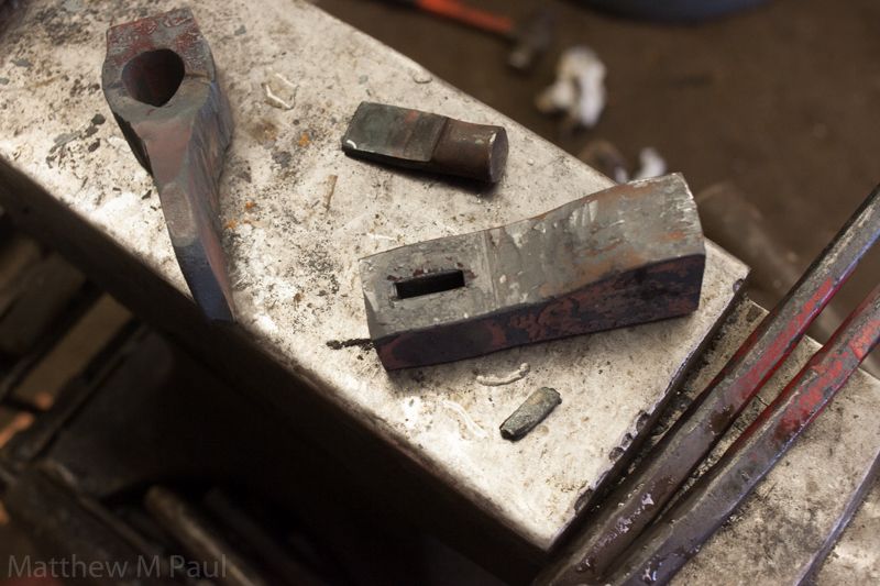
As it has been from the time that I started making this some years back, my work has been heavily influenced by that of James Austin and the work that he did with Jeff Pringle.I've tried many different methods and starting stock sizes and shapes, however I have found my work to be the most consistent by starting out with 1" square A36, about 4" long. The one side then gets "upset" to build up the material for the front portion of the axe, and the rear section stays about 1" square for the eye. Next the hole that will become the eye is hot punched slowly with hand hammers.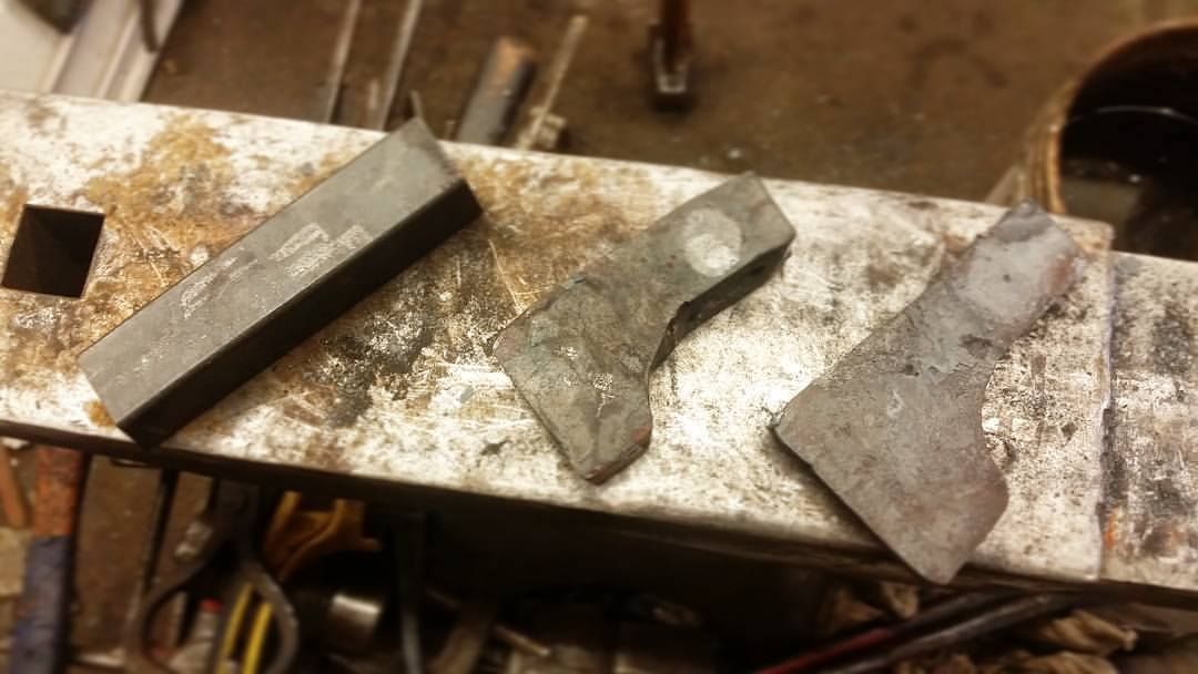 After the eye is punched, it is drifted out about 75% of its final size.
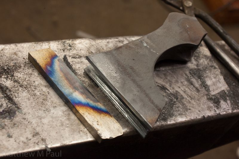
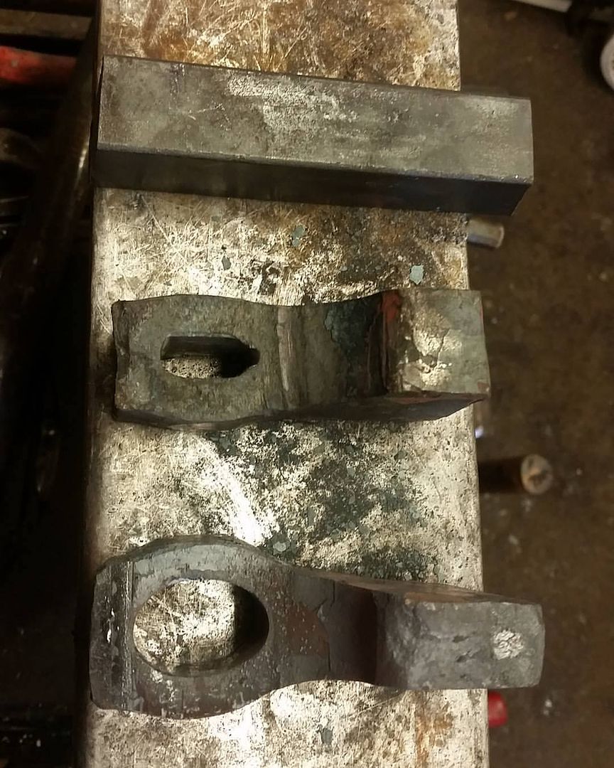 The edge is hot cut, beveled, opened and cleaned to accept the high carbon steel bit, which will then be forged to shape, and forge welded into the axe head.
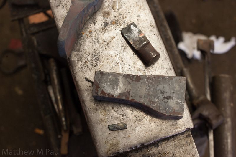
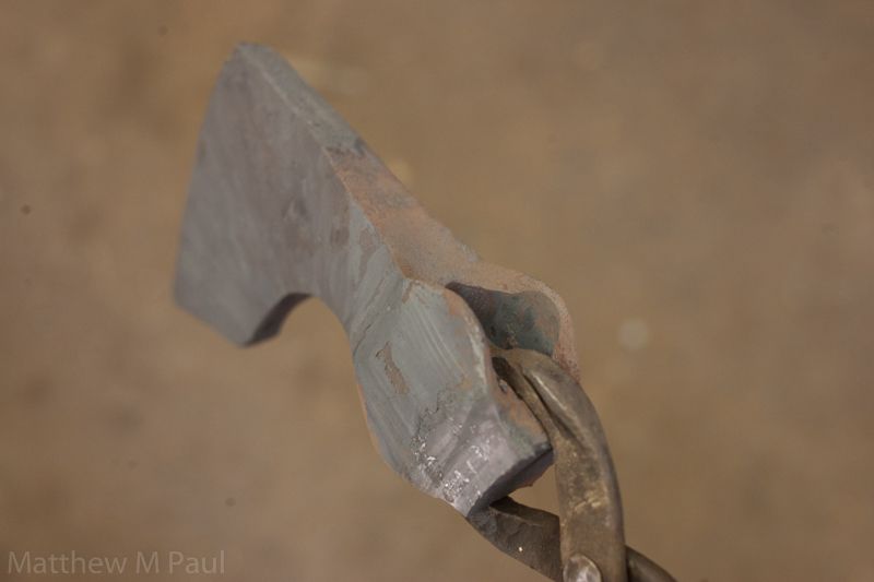
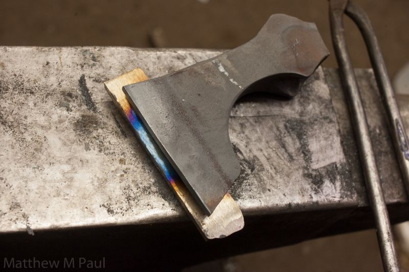
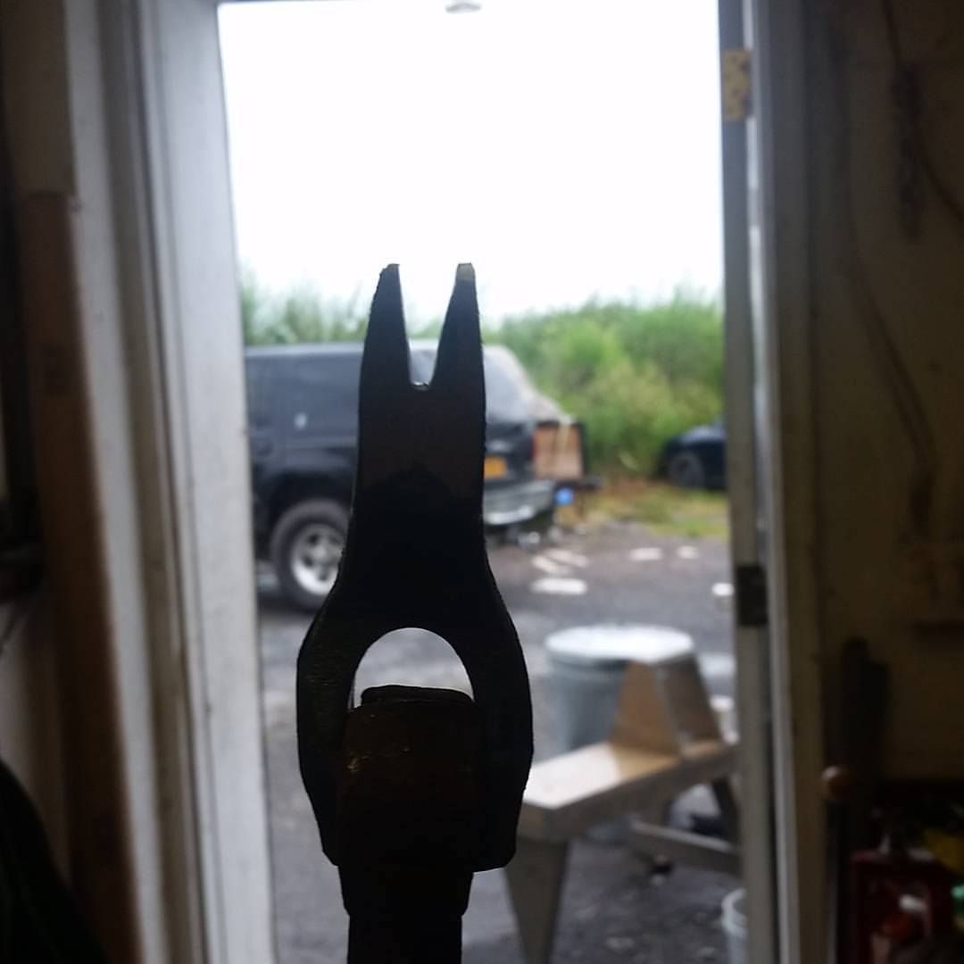 Here you can see the axe fresh from forge welding with a little clean up work to remove the excess bit material, and a little clean up around the edges. I normally have less material to remove post forging but it has been a long time since I forged one of these. You can also see the higher carbon material used for the bit showing black in the photo.
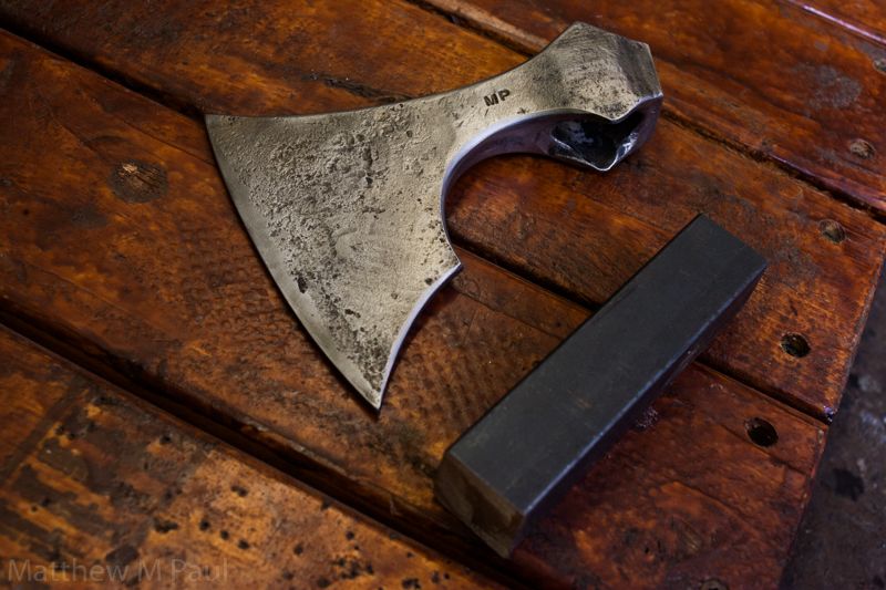
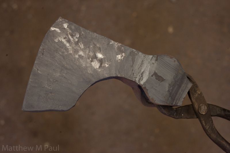
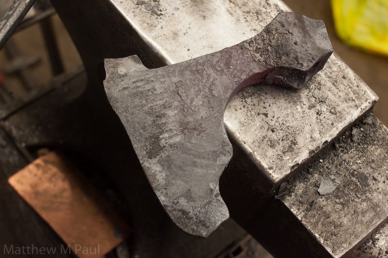
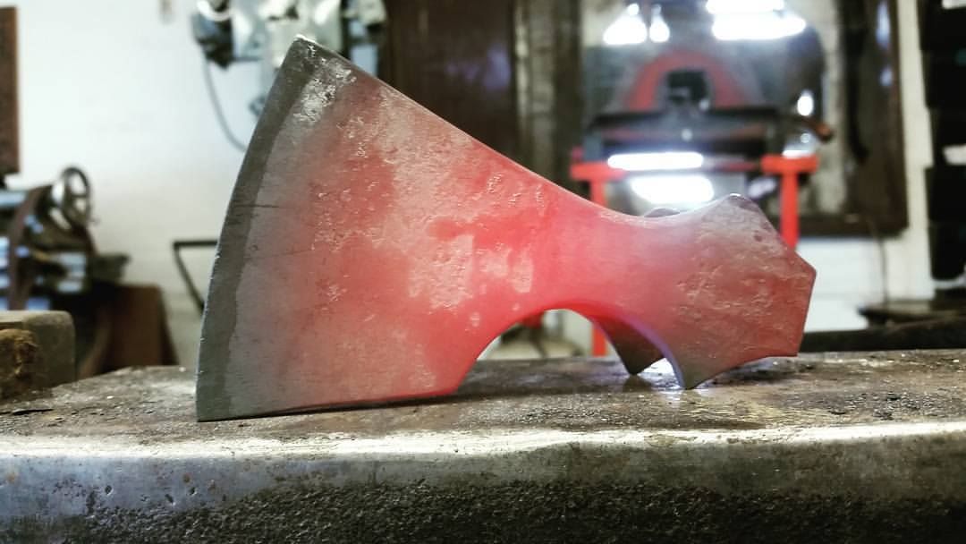 Cleaned up and etched, ready for heat treatment.
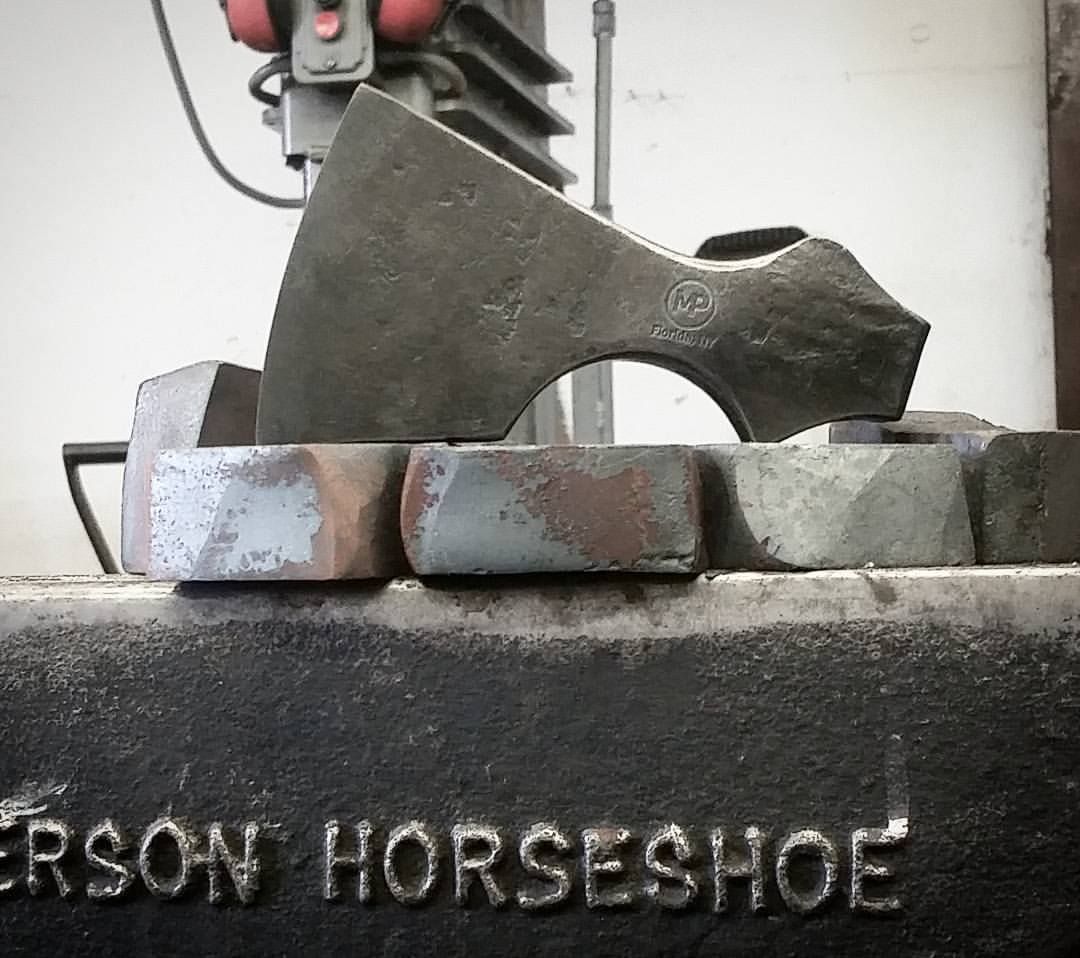 The heat treated axe with the material that it started out as. That's a LOT of hammer work.
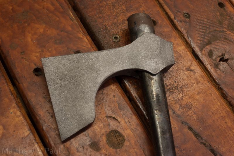
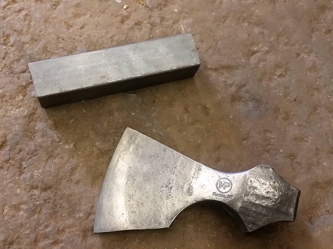 Test fitting the tapered handle:
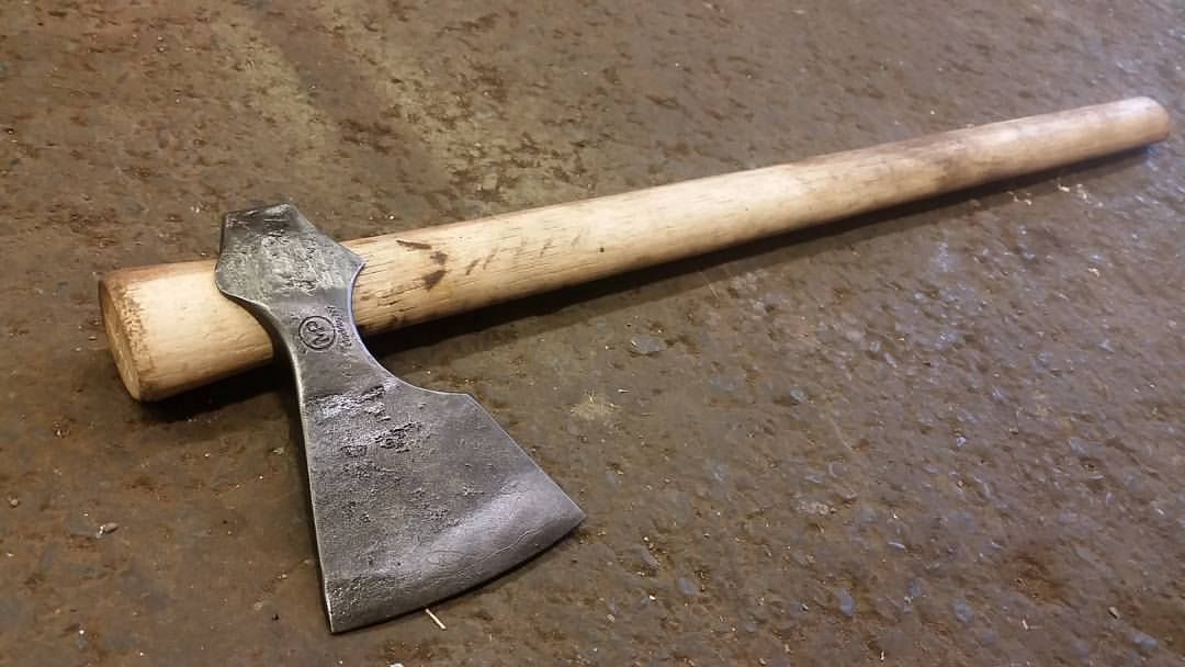 Here is the finished axe on the fire treated and oiled handle.
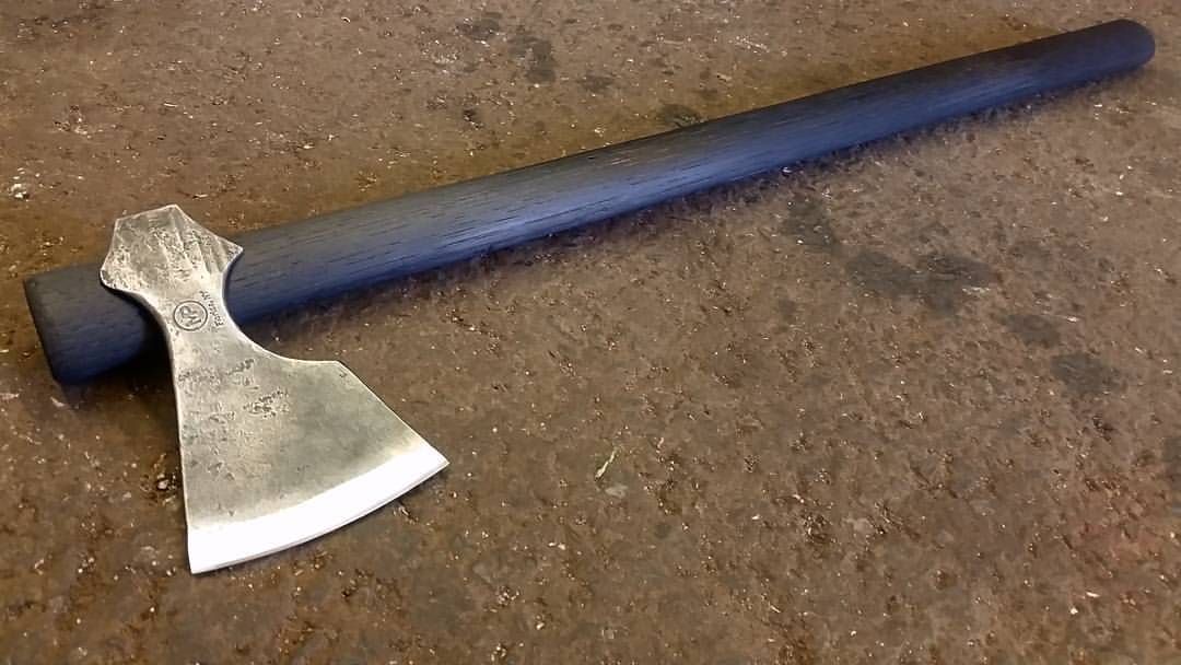 I took the axe out to clear out some shooting lanes where Ill be putting up a new tree stand this year for deer season.
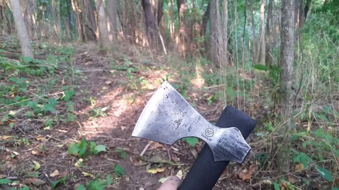
Thank you for having a look, perhaps next time I can take more detailed photos. -
I chisel barbs into the thin edge of the steel bit so when the orange hot body is forged down onto the cold edge, the barbs lock it in place
")
Nice axe btw

Thank you. That is how I have always done it, but I did not on this one and I was not thrilled with how it worked out, although it did work.
To deal with sliding you could always rivet the pieces together cold and then forge weld them---it's mentioned as a method over 100 years ago...
(and while cleft welds are common for this process; lap and even butt welds have been documented historically. Cleft welds work well when you do a wrap around and weld body)
I usually cut teeth into the bit, but I have riveted it before welding before. It worked well. The cool thing with doing it that way is there is a mechanical back up in the event that a weld fails in use, although I would not count it it. The history is always interesting.
Thank you for the excellent description of your process and the clear sequence of pictures. That looks to be a great design for the ax and will be striking when fully dressed. Great
work.
You are most welcome, and thank you. I'll post up a photo or two when it is finished, although the customer wants a rearward curving handle, not my ideal choice but that is what the want.
-
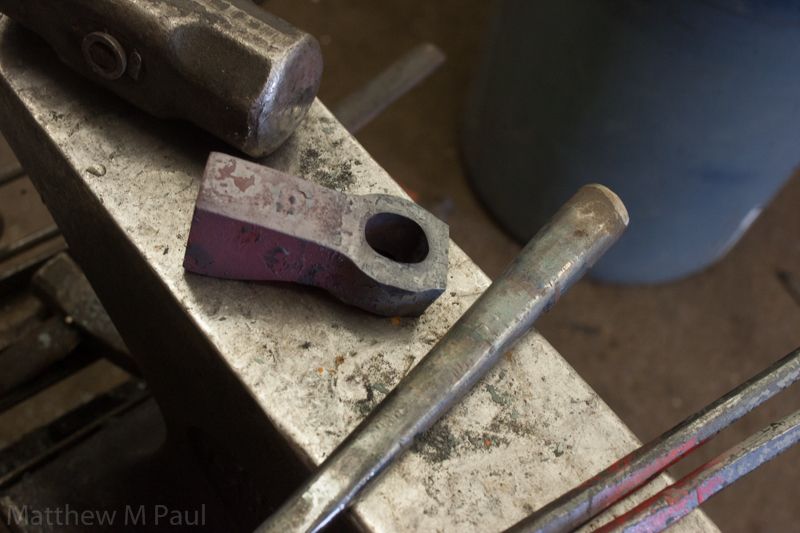
I've got this one ready for heat treatment. The body was forged from 1" square A36, and the bit forged and ground from 80crv2.
The first photo shows the axe ready to be heat treated, as well as the starting steel stock. A lot of the smaller steps are not shown, but this is what I had for photos.
So, the block is heated only on one half, and then upset to form the most basic of axe shape. I kept the stock 1" wide at this point, but upset the profile of it. Then the eye is punched. I did this on the home made hammer as I no longer have a striker around to help out on the axes. The eye is drifted close to its final size, and the "ears" are forged out a little, with the drift in eye. Then the bit end of the axe is forged out closer to the final shape, about half way between the starting size and the final shape, in both height and thickness. After that I let the head cool, blast it, and cut the edge with the band saw. I usually use a torch with the head clamped in a vice, and cut it with a chisel, but my torches are out of gas so I just cut the slit instead. The mouth is opened up and the bit is forged to shape from bar stock. I clean the bit, and the mouth, then heat, flux, and lightly seat the bit. This is the first time that I have done an axe without cutting teeth into the bit, so that it would bite into and hold in the mouth cut while forge welding, and I wont be doing that anymore. Once the pieces were hot to forge weld the bit would slide around in the mouth cut. So, I used a step block in the hardy hole to but the bit against while I welded it. It worked out just fine, but some more care was needed while welding. After welding the axe was drawn out some and then allowed to cool so that I could trim the excess bit material away, and finish the forging. Yes, I could have hot cut the material away, but it can be difficult to hold the tapered axe head, keep the cutting plate in place, and operate the hammer and chisel. Doing this operation is much easier with a striker. I need to forge a small cutter for use on the power hammer, and make a cutting plate to sit on the bottom die. The axe is finish forged to shape, cleaned up a bit on the grinder, blasted, and ready for heat treatment. It is in the kiln now being normalized.
-
If you really wanted to clean it up some, a little bit of sand paper and maybe a sanding block to soften the edges on some of the hammer strikes would probably do. But from the photo it does not seem to be bad at all, the round horn end of the face seems to be pretty smooth. That is a nice anvil though. I like that style. Have you done any forging on it yet?
-
I'm no expert, but I run about a 1/8" radius on mine. The next set that I make I will probably do a 1/4" radius on though. Also, your hammer is fantastic, and one day I wish to get an 2 piece 88 or a 1B. It looks great in the blue/black. Congrats on getting it!
-
What size is the current die plate? 3.5" square or 4??? and by bigger, do you mean wider front to back? longer?
Running the two bolts would allow a deeper die. the angle in which you make the dies has a lot to do with the size of die that you can fit on the plate.For example my upper die plate is about 3 7/8" wide, and I run a 3" x 2" die.
If I ran my dies at a 45deg angle instead of the approximate 30deg, I could fit much larger die blocks, an extra 1/2 wide. If I were to cut 1/4" from each corner of the die block, I could fit a 4" wide die.
You cant really run larger plates as the hammer still needs to travel up and down in the guides, unless the travel is not enough that the die plate goes within the guides. -
I just finished making a new set today, and saw this yesterday, so I took some photos. I do it basically the same way as Frosty, but like he said, there may be better ways.
Started with 2" 1045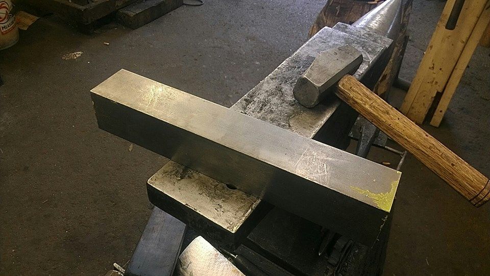
Cut it to 3" lengths and milled half of the dies to the angle that I wanted.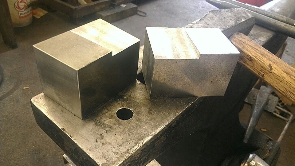
Radiused the edges with a file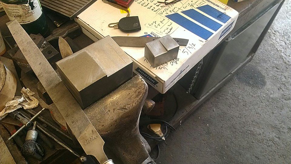
Chamfered the bottom of the dies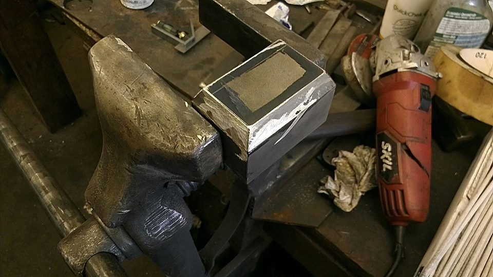
Clamped the top die plate and block to another piece of steel to help minimize warpage when welding (Im no expert welder)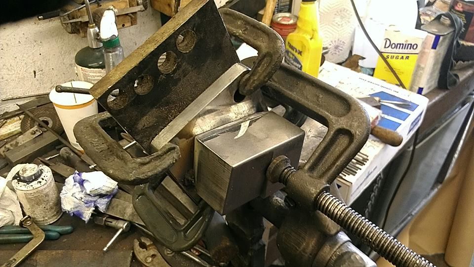
Welded the top die, bolted in place, bolted the bottom die plate in place, and tacked the bottom die block so that it lined up.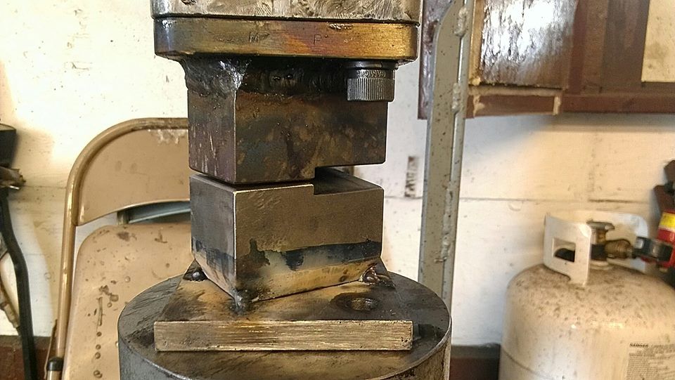
And here they are, heat treat as required.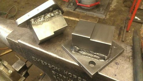
-
yeah, I agree. The bolt on dies are ok, and cheep to make. But, If I make another one I'd spend the extra time and coin on making it so that it took normal style dies. Good to hear that ya got it all fixed up.
-
It wouldn't be a bad idea to clean the die faces and sides really well with scotchbrite or some light sand paper so that you can see if the welding actually effected the temper or not. I use 1045 for mine so the heat treat is a bit different. But, if you have the time it may not be a bad idea to remove the entire die block from the plate, Put a nice 1/2" chamfer on the bottom of the die block (like you said), and then rebuild it with several passes. The problem with re welding the whole block, especially with 1/8" 7018 is the heat build up. I'd bet that you would soften them right up. I'm not sure what heat range you use welding 1/8 7018 but I tend to run in the 145 AC range, give or take, and that imparts some serious heat on a small piece like that. Best thing you could do is go for it and see what happens.
The temper temperature called for on 4140, for around 50rc is only 400deg.
If you don't have access to a kiln, I'd probably just weld it and call it good. If you do have access to a kiln, I'd probably just re heat treat the dies. -
Looks good ForgeMan32!
Also, another video of the hammer: -
I finally got around to making some rounding dies for the hammer. Here is giving them a test run.
-
Thanks yall. The 3/16" round "fullering" was done with a chainsaw file, and the thin line next to it, a triangle file. You can see file marks on the piece if you look closely.
-
That looks great!
-
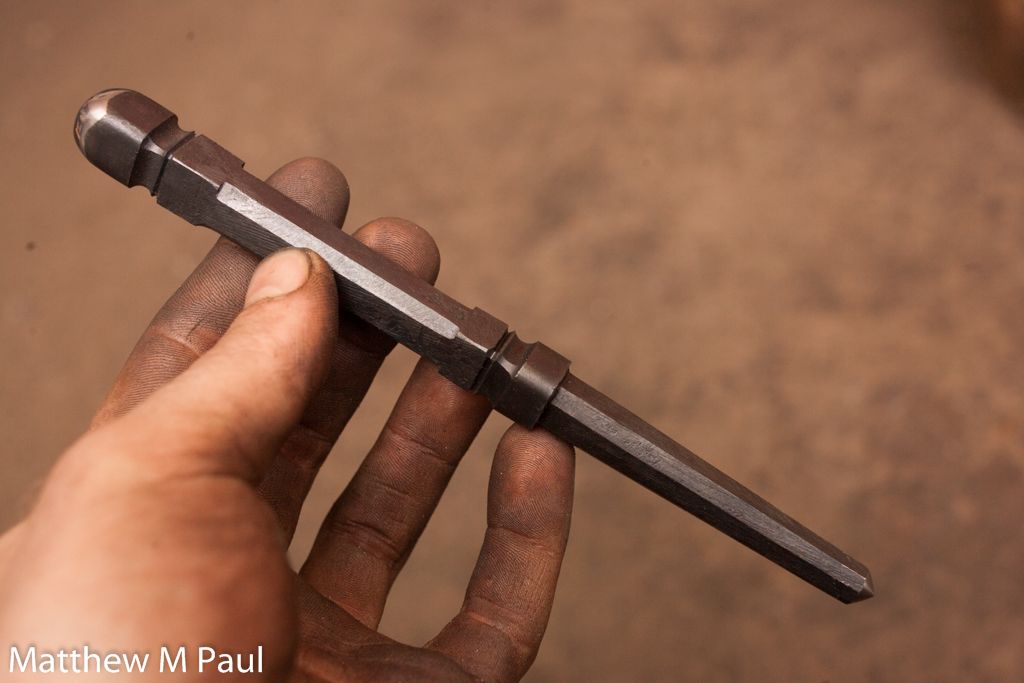
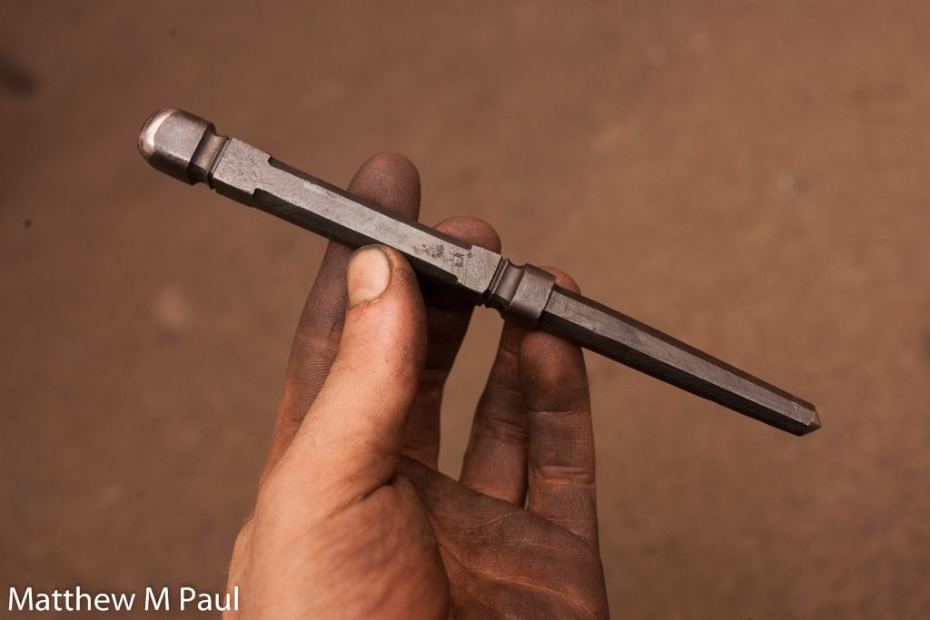
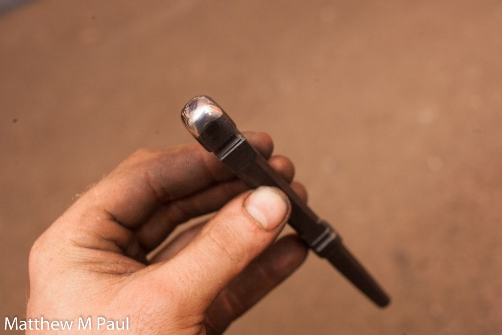
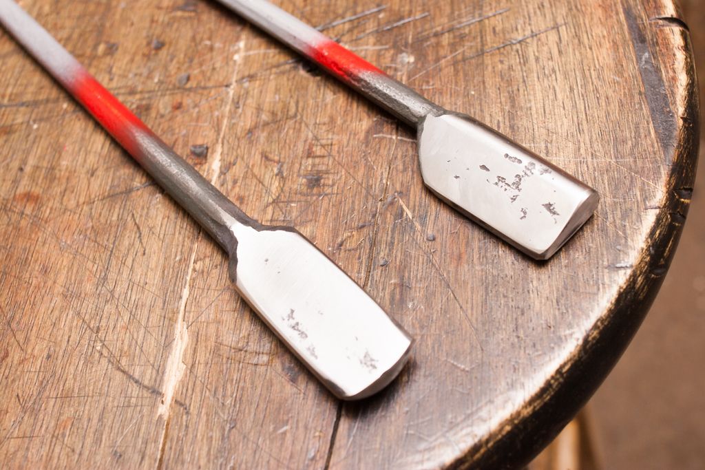
I just finished this center punch for a guy in Cali. Forged from 3/4" W1 round stock. The forging was done on the power hammer that I finished building a few weeks ago. This punch was inspired by Seth Gould's work, who was in town last week at the "Center for Metal Arts". I got to see his work but did not have the time to speak with him.
-
If I was buying new steel to make one with it would be S7, many people use H13. I have never used it so that is why Ive been sticking with S7, it works for me. My hot cut is made from 1045 because I had a good amount here in the shop. I made it a bit more robust than I would if it was S7, and I have had no problems hot cutting mild, W1, W2, 80crv2, etc...
-
No need to be artistic to make things, although it sure does not hurt. Yes it takes a long time to get good at, and even longer to get great at forging. It seems to be a profession where you can never learn enough. There are so many variations and specialties that you could spend a lifetime doing this and still have things to learn, it seems. But, It does not take a long time to learn enough to make things. very little time actually before you can make functioning items. From there on out its all about improving and learning what you want to or need to,
-
The one guy that strikes for me on occasion, swings like that with a 6# head on a 24" handle. I sure wouldn't do that with someone that I did not trust though.
-
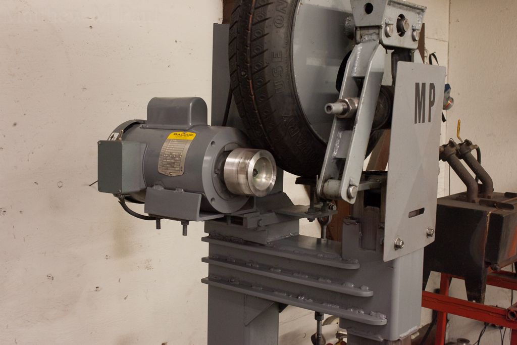
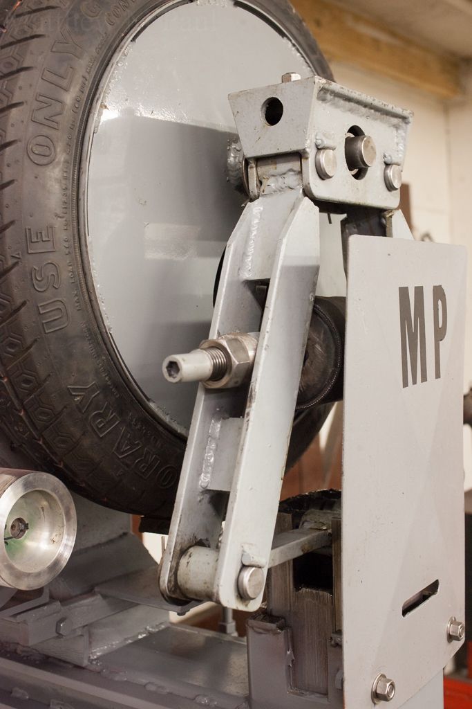
The plans call for a trailer spindle, but I went with the FWD car hub as the wheel that I had was of that bolt pattern.
Ive had no problem using tooling so far, but I have not punched any eyes on hammer stock or anything. As far as the break and motor engagement, if it is adjusted properly.. I think that the hammer has control that rivals that of the self contained air hammers that Ive used.
Any steel yard can get you the avil stock, and all of the yards around here have it in stock.
If you don't have the plans yet, I'd suggest getting them. Lots and lots of information in there. A small investment for what you get out of it.
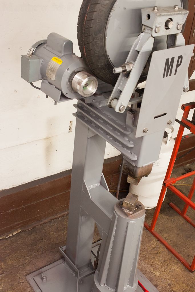
The linkage flex was easily resolved by reaming the treadle pivot and installing some bronze phosphate bushings with built in thrust washers. And, by bracing the treadle linkage. -
Thanks.
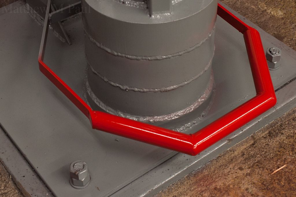
Replacing the 1/2" plate with 1" is most definitely something that I would do if I built another one. I may brace the base plate to remove some deflection.
The motor spot weld issue I did not see as I had to make the mounts for my motor as it was a 56c frame.
I have grease fittings and all that but I have not put them in yet, nor have I drilled the holes to oil as the plans have said. I wanted to run it first and see what I thought. It's really quite siimple to oil it daily so I think that I'll leave it for now.
As far as welding to the wheel, it is one of the most simple parts of the build. I completely removed the tire from the wheel when I did this. These small tires are pretty easy to take off with spoons, and if you dont want to do that or don't have access to a tire machine, a tire shop would do it for about $10. As far as the ease of replacing the tire down the road, that's fairly simple as well, the hammer can stay in the tube so you just block it up, Back out the hex bolts for the spring tension, remove to spring, two clevis pins, two set screws, and unbolt the hub. The wheel does not need to be removed from the hub to change the tire.
I am a tool maker as well so I deal with various "high carbon" steels from 1075 to 80crv2, W1, W2, etc... as well as medium and low carbon steel. It's noticeable forging tool steel vs mild under the hammer, but it still beats doing the heavy work by hand as far as labor goes.
Also, if I made another I would think about building it on a 2' by 3' wide piece of 1" instead opf the 2' square, and adding lateral supports to the main column. But Ive got a problem with over doing things....
I also did some more bracing last night. The 1/2" round stock that is used for the treadle linkage, and the turnbuckle without a bottom lock nut has a lot of play in it.
https://www.youtube.com/watch?v=y3NY83x7FzA
https://www.youtube.com/watch?v=90PqZYomNKg -
eThank you fellas.
Stormcrow, the forging videos that I have are not too hot but here is one from last night. Im by no means a pro on a power hammer. In this video is only the 3rd time that Ive used one")
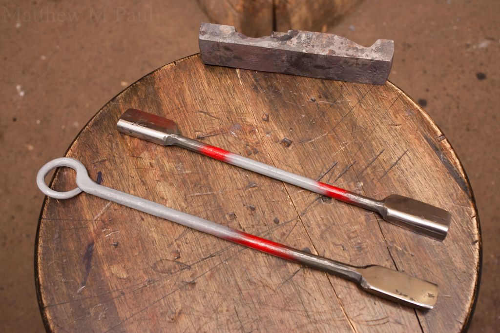
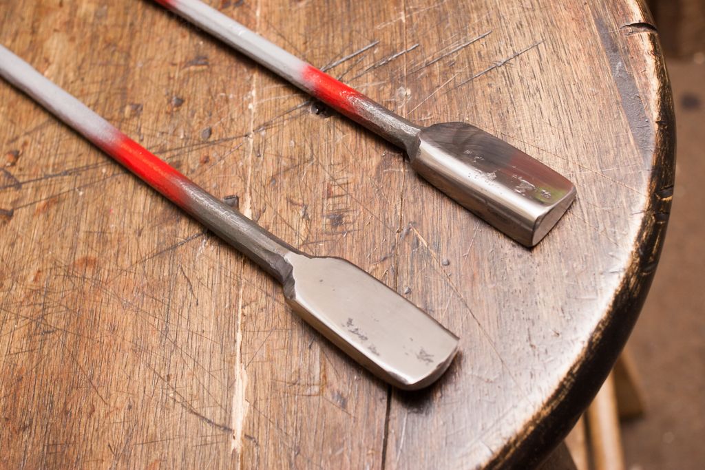
This is forging down some 3/4" round W1 for some hammer tooling... I might as well post the photos of those too!
I made a swage block to form the ends of these tools. I used the corner of my anvil and some round stock for the double sided one, and some 1" round, 3/8x 1" flat, and 2"x1/4" flat as top tools to make the swage for the single sided tool. The handle diameter on these is 5/16"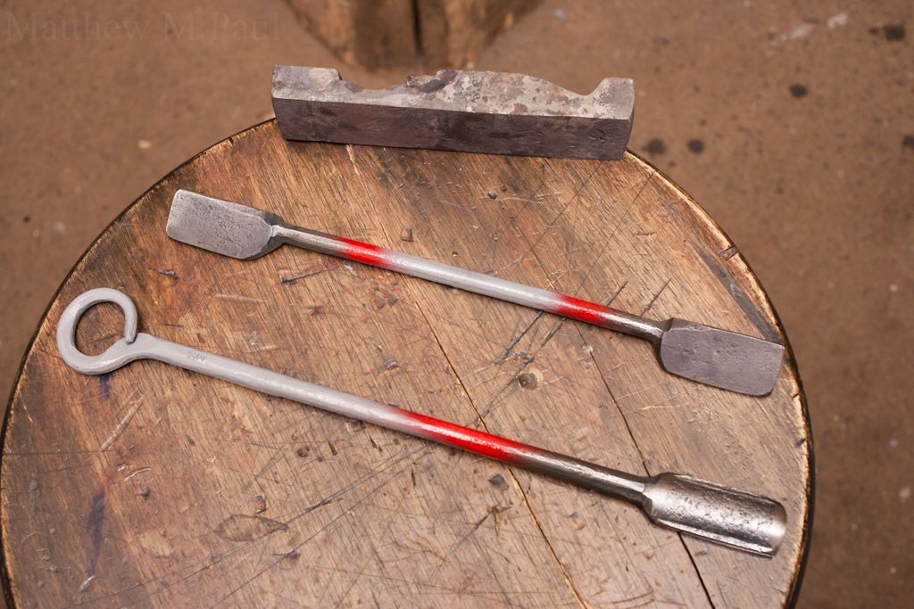
-
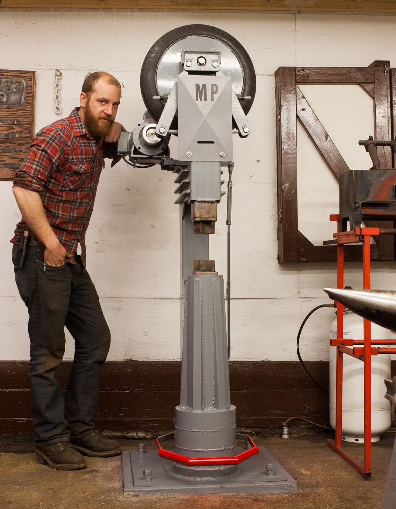
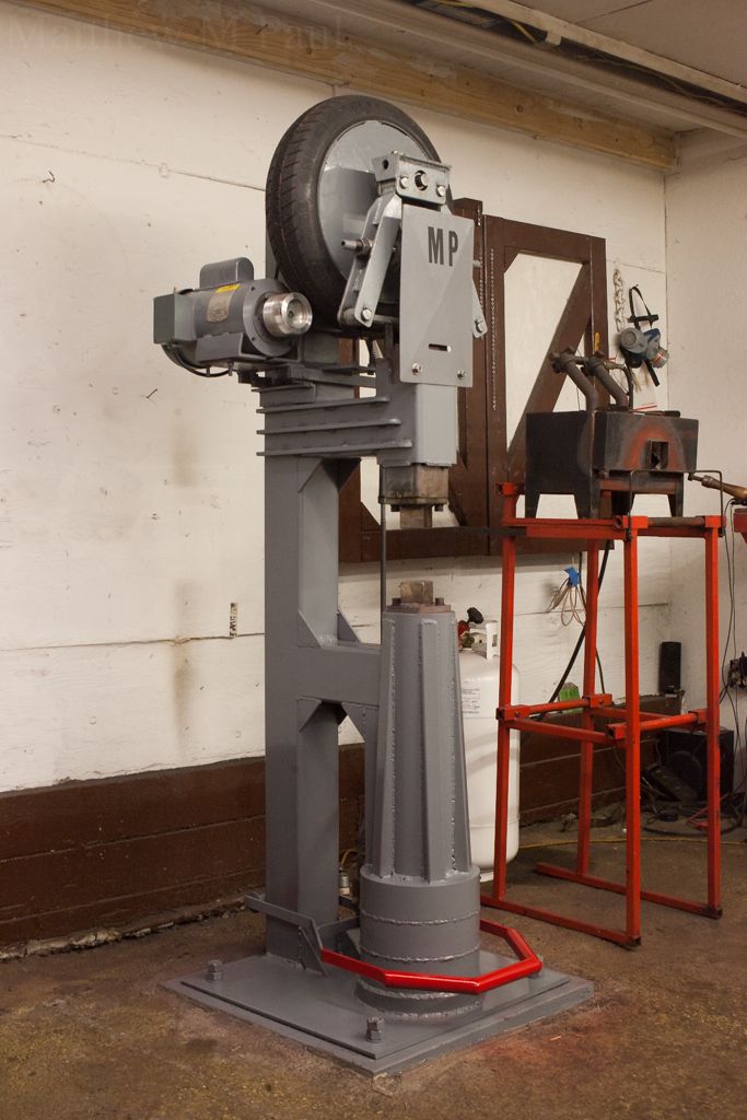
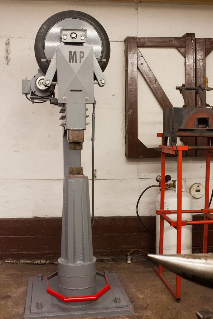
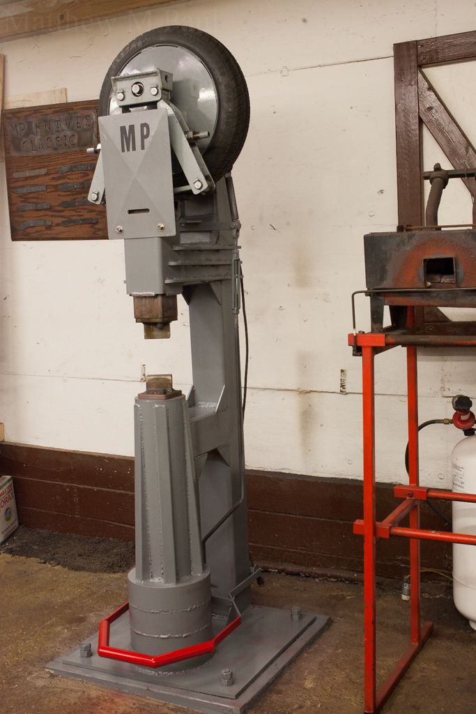
I just finished building my Mechanical Power Hammer. I spent the last week building the frame and finishing up this project. The ram is 50lbs, with a 450lb anvil. The hammer has amazing control. I added a lot of gusseting and supports, as well as a different treadle design. I lowered the anvil and column height, used taller dies, and a bunch of other smaller changes, but no changes to the linkage/ram design.
This is extremely exciting and a big step. 4 years of hard work has landed me here. I never would have dreamed of the day that I would own a power hammer, much less build my own. I think that I have about 160 hours invested in this thing total. So much welding. 2-3 days straight of welding, 20lb of welding rod, and about 3lb of mig wire. I still want to wire another switch and brace the treadle linkage but it works, and well.
-
I like that. Nice job.
Forging a "Type D" Inspired Axe.
in Axes, Hatchets, Hawks, Choppers, etc
Posted
Thank you very much Benton