

mrichard76
-
Posts
23 -
Joined
-
Last visited
Recent Profile Visitors


-
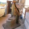
Anyone know what this tool is?
mrichard76 replied to mrichard76's topic in Tools, general discussion
Thanks BT! Still trying to envision exactly how this works though.... -
Anyone know what this tool is?
mrichard76 replied to mrichard76's topic in Tools, general discussion
Yes that is a 5 on the part actuated by the vertical cam. Seems to be a real mystery here! Really bugging me as to what this is... -
Anyone know what this tool is?
mrichard76 replied to mrichard76's topic in Tools, general discussion
Don't see any other numbering on it. -
Anyone know what this tool is?
mrichard76 replied to mrichard76's topic in Tools, general discussion
On the 4th picture you can see allot of hammer marks. Also you can see numbers on multiple parts in the other photos. Can't make out the text(patent?) and the date is not so clear either. -
2 Chambersburg #200 Steam Hammers
mrichard76 replied to Steampressowner's topic in Power Hammers, Treadle Hammers, Olivers
Here's a picture of the inlet plumbing if this can tell anything. -
2 Chambersburg #200 Steam Hammers
mrichard76 replied to Steampressowner's topic in Power Hammers, Treadle Hammers, Olivers
When I was checking out the piston and rings on the 400, I think the rings weren't any more than an 1/8" thick. I would imagine (with out a whole lot of wear) you wouldn't have more the an 1/3 of the piston ring thickness exposed outside of the piston groove while in the cylinder bore. This would give you around 0.042" clearance. This is just estimation though... I measured my resevoir and it is a 600 gallon tank. -
2 Chambersburg #200 Steam Hammers
mrichard76 replied to Steampressowner's topic in Power Hammers, Treadle Hammers, Olivers
The 200 lb still has it's original brass ID plate stating air operation at 80-100 psi. The 400 has no remaining info. Is there a way to determine if it was indeed built as a steam hammer? -
2 Chambersburg #200 Steam Hammers
mrichard76 replied to Steampressowner's topic in Power Hammers, Treadle Hammers, Olivers
Will have to get an accurate measurement of the reservoir. Mike, I think the iron's gonna get cold between my forge in Louisiana and Georgia! Maybe you could bring your 500 lb Bradley down to Louisiana and I won't need a compressor! -
Anyone know what this tool is?
mrichard76 replied to mrichard76's topic in Tools, general discussion
Hahaha! Will try to get some more pics. -
Anyone know what this tool is?
mrichard76 replied to mrichard76's topic in Tools, general discussion
Doesn't look like one to me. Also has some decorative refinements. Maybe it was part of a larger machine/tool? -
2 Chambersburg #200 Steam Hammers
mrichard76 replied to Steampressowner's topic in Power Hammers, Treadle Hammers, Olivers
20 horsepower and around 500 gallons of reservoir. Reservoir will need to be relocated as close as possible to the hammers. Will also be running the 200 lb utility but not simultaneously. -
2 Chambersburg #200 Steam Hammers
mrichard76 replied to Steampressowner's topic in Power Hammers, Treadle Hammers, Olivers
I have all the originals but the got really screwed up by whoever disassembled the hammer years ago. The all thread is just temporarily holding the upper assembly in place - not under power :-)) I'll be using 1" grade 8's for the permanent ones. I love this hammer too! Just hope the compressor and reservoir can handle the hammer! -
Anyone know what this tool is?
mrichard76 replied to mrichard76's topic in Tools, general discussion
No Patent numbers that I can see. The angles look like it could be used for plow points. Maybe to swage down the points??? -
Anyone know what this tool is?
mrichard76 replied to mrichard76's topic in Tools, general discussion
That was my thought at first but there is no blade or bypass. It is blunt looks like some sort of clamp. The two cams operate at 90 degrees to each other, but are skewed at 45 degrees in another plane. -
2 Chambersburg #200 Steam Hammers
mrichard76 replied to Steampressowner's topic in Power Hammers, Treadle Hammers, Olivers
Got the cylinder/ram assembly mounted back on the frame. Opened up the cylinder and everything looks good inside with no broken rings or gouging. The frame was outside laying on its side for the last few decades after failed attempts of removal by the local scrappers. The whole upper assembly was kept under a carport out of the weather. I found a small brass plate on riveted on the frame marked G.S.A. 5-1931. Does anybody know what that might be? The General Services Administration was established in 1949...