Dillon Sculpture Posted June 17, 2012 Share Posted June 17, 2012 Oops! Thats a big hole... Finally, what brought me to IFI years ago was information from the late great Mr. Sarver about his "little" steam hammer. Full circle now and I am installing both my 750 and 200 in the shop. Cut and excavated the holes last week and I am building the rebar cages with the hopes of getting some mud this coming week. I also will be adding the modifications Grant used to on his hammer if I can figure it out... Quote Link to comment Share on other sites More sharing options...
Sam Salvati Posted June 17, 2012 Share Posted June 17, 2012 Amazing.............. Quote Link to comment Share on other sites More sharing options...
macbruce Posted June 17, 2012 Share Posted June 17, 2012 UMPH ! Quote Link to comment Share on other sites More sharing options...
iron woodrow Posted June 17, 2012 Share Posted June 17, 2012 onya mate! You gunna run em on steam? Cause your gonna want a BIG compressor if not! Cant wait to get my ole girl thumping. We can carry on mr sarvers knowlege as best we can! Quote Link to comment Share on other sites More sharing options...
macbruce Posted June 17, 2012 Share Posted June 17, 2012 Danger! You are about to exceed the ''Sport forging'' limit [anything 500# or under or so I've heard it called] by 250 lbs, you're into the Industrial realm now........ B) Quote Link to comment Share on other sites More sharing options...
Dillon Sculpture Posted June 17, 2012 Author Share Posted June 17, 2012 I never did add them up, 1700 lbs. combined! Thats just shameful B) My Deutz diesel driven Atlas Copco air compressor puts out almost 400 cfm, should run em both at the same time. I also have a 30 cfm I will pipe over to a 500 gallon tank for short pops on the 200. Quote Link to comment Share on other sites More sharing options...
iron woodrow Posted June 17, 2012 Share Posted June 17, 2012 you dont have steam hammers. You have diesel pneumatic hammers! Quote Link to comment Share on other sites More sharing options...
John Larson Posted June 17, 2012 Share Posted June 17, 2012 Danger Dillon, this looks super. Keep us posted, please. Quote Link to comment Share on other sites More sharing options...
Madmike Posted June 18, 2012 Share Posted June 18, 2012 6 feet under... To bring 'em alive :lol: I agree with John but would add :"don't forget the videos" :P Quote Link to comment Share on other sites More sharing options...
Jim Kehler Posted June 18, 2012 Share Posted June 18, 2012 Looking forward to seeing those in action :) Quote Link to comment Share on other sites More sharing options...
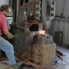
Dillon Sculpture Posted June 18, 2012 Author Share Posted June 18, 2012 http://www.youtube.com/watch?v=SATwWtvT7uQ&feature=youtu.be Here are a couple older videos of the hammers. I had the 750 at my old shop but its been disassembled since I moved. Some specs. on the air compressor 6 cylinder 100 hp. air cooled diesel, each cylinder and head is individual unit so you can easily replace a single part. Atlas Copco piston compressor has two 8 1/2" low pressure and two 5 1/4" high cylinders. The hole unit weighs 5600 pounds! I plan to cover with a shed to conceal the noise as it tend to be louder than the hammers. I can run it all day for $20-30 bucks. Quote Link to comment Share on other sites More sharing options...
KjZitur Posted June 18, 2012 Share Posted June 18, 2012 Hey Danger, I to am looking forward to seeing the vid's of your hammer in action. Wish I could see them up close!! should be exciting............. Quote Link to comment Share on other sites More sharing options...
Dillon Sculpture Posted June 18, 2012 Author Share Posted June 18, 2012 Hey Ken, you must have read my mind... How about some feedback on Grants hammer modifications? Can you tell what is going on there? Quote Link to comment Share on other sites More sharing options...
nonjic Posted June 18, 2012 Share Posted June 18, 2012 neatest foundation holes I have ever seen! top work :) looking forward to seeing this thread progress! Quote Link to comment Share on other sites More sharing options...
John Larson Posted June 18, 2012 Share Posted June 18, 2012 The video material is great. I found it interesting that most of your control is via the steam throttle valve lever rather than the other lever. Never having run one nor paid close enough attention when I've had the chance I somehow thought the opposite would be true. Quote Link to comment Share on other sites More sharing options...
ptree Posted June 18, 2012 Share Posted June 18, 2012 In my experience the throttle is a throttle for any working fluid. Steam hammers often had a tup at idle to keep the heat in the steam piping and the boiler pressures steady. Tup at idle is a waste of air if using a modern air compressor. Most of the valve chests on the older steam hammers had fairly loose fits as the steam needed to flow anyway, see above. For air, most install modified valve elements that have elastomeric seals. Think Parker Poly-pacs. Looks like a great project, enjoy. Quote Link to comment Share on other sites More sharing options...
Dillon Sculpture Posted June 18, 2012 Author Share Posted June 18, 2012 John, actually it IS the other way around, less movement on the throttle more on the motion valve. The 200 in the video was the only time I had used it but it had great control. Another 100 hr. I should be able to whittle wooden teeth :huh: Ptree, when I rebuilt the Niles it had about 3/8" clearance in the motion valve, I just closed down the tolerances to a few thousand, no seals, runs great! Quote Link to comment Share on other sites More sharing options...
Jim Kehler Posted June 19, 2012 Share Posted June 19, 2012 Hi Michael, don't think I'd seen that video of the 750 before . Your guys look eager enough and I think with a bit more practice you would really like working with a driver. B) Your driver is giving you what you'd get with a typical treadle set-up, better if he kept the throttle open and used the motion lever. With suspended stuff like that its good if he can hit every second stroke(a shorter non hitting stroke in between) it lets you get yourself set a bit better. Its also nice if your crane operator has some forging experience so he knows what it feels like when the piece isn't flat in the dies :o I know Grant was feeding a small amount of air into the motion valve body in order to get it to idle, other than that I'm not sure. Quote Link to comment Share on other sites More sharing options...
Dillon Sculpture Posted June 19, 2012 Author Share Posted June 19, 2012 Hey Jim, we were WAY green for sure, still am for that matter. I had never seen a steam hammer much less run one when this one came my way. I had noticed Kallsmeden1 using this method you described in his videos, he obviously forges all day every day. The 1" air line pumped in the valve chest is about as far as I got as well, linking the motion valve to the handle on the left that he pulls down is key. He also had a chain that ran from that handle to his treadle. Quote Link to comment Share on other sites More sharing options...
Jim Kehler Posted June 19, 2012 Share Posted June 19, 2012 I think these are two different things, the air line and ball valve are to make it idle, the lever and chain to the treadle are so you can operate the motion valve from the front of the hammer either with the lever or the treadle. Quote Link to comment Share on other sites More sharing options...
Dillon Sculpture Posted June 19, 2012 Author Share Posted June 19, 2012 Rebar in, ready for mud. I will pour a 4 yard shelf in the big hole set 3' of oak the anvil then pour another 4 yards around that. Just a yard under the 200. When I bought this hammer it was derelict and missing a very important piece, the sow block (scraped probably). So I built one, I used my shaper to true up 9-6" billets and welded them together. After welding they warped and I never had a way to true them back. Long story short we took a field trip to Capital machine to drop the sow block off for machining. This place rebuilds rock crushers, uh... made my stuff look like toys! The first pic is the bridge from their 600 ton horizontal press they accidentally broke OOPS! The other is self explanatory... The lathe has a 30 ton bridge crane over it, I presume thats how they got it in there. Quote Link to comment Share on other sites More sharing options...
John Larson Posted June 19, 2012 Share Posted June 19, 2012 Ptree, not to speak against you but rather to just add my 2 cents, I'm basing my conjecture on the 3-position aspect of the spool valve in steam hammer sketches I've seen. Once it is "steam locked" at the position set by the lever on the spear, that lever has to move to disrupt the equalized forces above and below the spool. Though my observation of the 750 video belays that. Also I'm considering Ken Z's valving and linkage. He uses a 3-position spool valve. His treadle sets a target and the tup moves to it when his is in the short slot adjustment and to it and beyond when he is in the long slot adjustment. He tends to keep his air valve at a fixed opening. In my humble opinion, of course. Quote Link to comment Share on other sites More sharing options...
iron woodrow Posted June 20, 2012 Share Posted June 20, 2012 the throttle only adjusts the flow, not the motion. so basically on my machine, which has no reciprocation built in, if you only use the throttle, you get one thump, and a lot of steam loss..... when i add the reciprocation mechanism/ sword it might be a different story.... ill find out soon enough! Quote Link to comment Share on other sites More sharing options...
Madmike Posted June 20, 2012 Share Posted June 20, 2012 I love this thread, blacksmith porn and mind food together :) Can't wait to see your reciprocation add Woody ;) Quote Link to comment Share on other sites More sharing options...
ptree Posted June 20, 2012 Share Posted June 20, 2012 John Larson, on the Eries I was around they had a treadle and lever, both performed the same function, and they had a spear to provide the tup recip. The spear system had a movable target so that the distance of tup was set. On ours the the treadle served as both motion and throttle. Hit the treadle a little and the tup travel moved down closer to the dies some and the speed picked up some, tromp the treadle and bang you got full stroke, full throttle. These were all closed die machines but were used open die on the edge of the dies to draw out tong holds on the bigger billets. Quote Link to comment Share on other sites More sharing options...
Recommended Posts
Join the conversation
You can post now and register later. If you have an account, sign in now to post with your account.